
Britain 637
A.D. 1862, 10th March. N° 637
Breech-loading Fire-arms.
(This Invention received Provisional Protection only.)
PROVISIONAL SPECIFICATION left by Marc Antoine Francois Mennons at the Office of the Commissioners of Patents, with his Petition, on the 10th March 1862.— A communication from Salloum Dandah (of Lebanon, in Syria), residing at St. Maur (Dept. de la Seine), France.
I, Marc Antoine Franiois Mennons, of the British and Foreign Patent Offices, 39, Rue de l’Echiquier, Paris, in the Empire of France, do hereby declare the nature of thrsaid Invention for “Certain Improvements In Brrech-Loading Fire-Arms,” (a communication,) to be as follows:—
The Invention communicated to me consists in an improved combination of charging and discharging mechanism for breech-loading fire-arms, the object of which is to permit of enlarging the calibre and multiplying the repetitions without undue increase of volume and weight while reducing the escapes and risk of accidental explosion inherent to revolvers and similar arms is at present constructed.
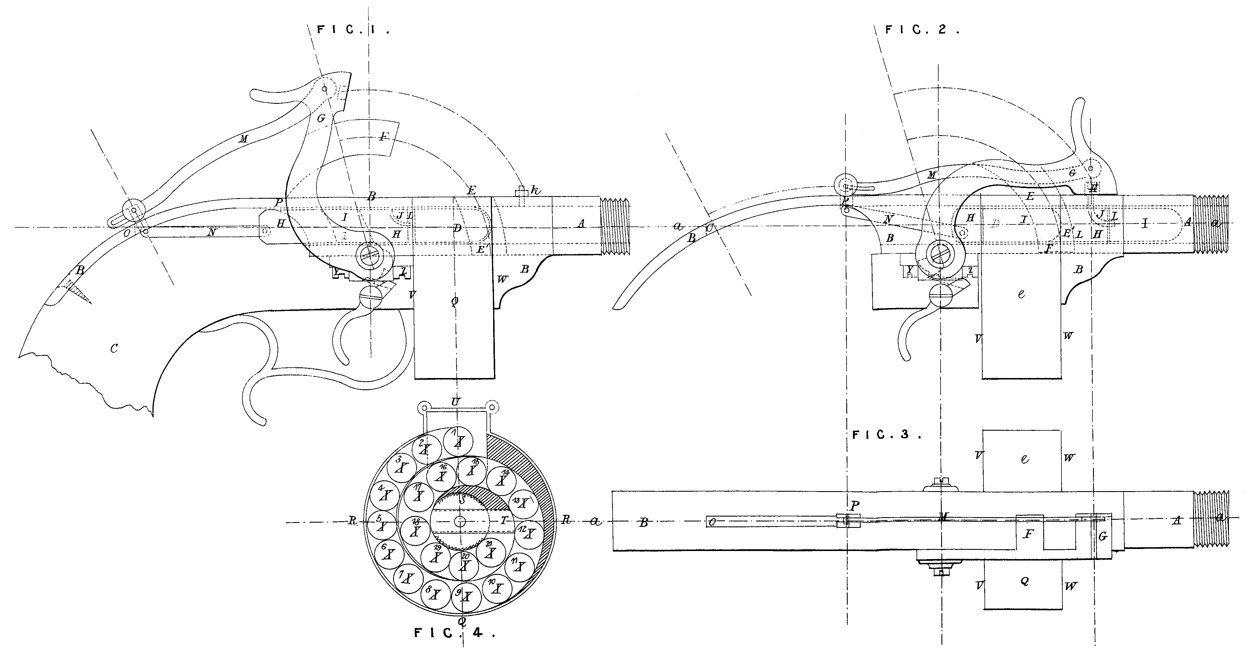
Figure 1 of the annexed Drawing represents the principal details of the improved mechanism opened for the reception of the charge ; Figure 2 represents the position of the same at the moment of the discharge ; Figure 3 is a plan of the same through the line x, x; Figure 4 is a cross section of the cartridge magazine. In all these Figures the corresponding parts are indicated by the same letters of reference.
A is the action chamber of the arm screwing into a barrel of ordinary construction, and forming part of the metallic setting B, B, B, to which is adjusted the stock C. D is a port opening cut through the side of the barrel setting behind the chamber A, to the size and form of the cartridge employed; E, E^1, are two oblong apertures cut through the centre of the barrel setting above and below, and corresponding with the stop bar F, which forms part of the cock G; H, H, is a piston through which is pierced a similar aperture I, I, also corresponding with the stop bar F. In the fore extremity of this piston is pierced a curved passage J communicating when the mechanism is closed with the cap pillar K, and terminated by a tubular cartridge piercer L. M is a metallic bridle articulated by one end to the head of the cock G and by the other to the horizontal connecting rod N, the free extremity of which is in its turn articulated to the back of the piston H. Between the points O and P a longitudinal groove is cut through the stock and mountings to serve as slide way for the connecting rod in its to-and-fro motion. Q is the cartridge magazine, seen apart in the cross section, Figure 4. This magazine, constructed on the same principle as the well known percussion cap primer, is composed of a metallic cylinder R, R, partitioned internally to form a spiral canal, and fitted with a steel spring coiled in a barrel S, on which is mounted an extending lever T. The cylinder is closed by the discs V, W, one of which is moveable at will for the introduction or withdrawal of the cartridges X. The latter are ranged side by side in the spiral canal, the mouth of which corresponds with the port D of the barrel setting when the magazine is secured in position by the clasp U, as seen in Figures 1, 2, 3. Y, Z, indicate the position of the lockwork, which, if so desired, may be constructed to raise the hammer by the trigger pull, as in ordinary repeating arms.
The caps may be supplied to the pillar K either by the hand or by a primer of any convenient description mounted on the barrel setting. On cocking the arm constructed as above the piston H is drawn back by the bridle M and connecting rod N to the position shewn in Figure 1, leaving the apertures D, E, and El completely open. At this moment the cartridge X^1 nearest the mouth of the magazine canal is forced by the action of the coiled spring on the lever T to pass through the port D into the barrel setting, its place being at once occupied by the second cartridge X^2 of the same range. On pulling the trigger, the cock G in its down stroke carries forward the piston, which in its turn forces the cartridge into the action chamber A. At this point the apertures I, E, and E’ of the piston and settings correspond exactly with each other, and are traversed together by the stop bar F, by which the piston is keyed firmly into the position shewn in Figure 2, thus forming the breech piece of the arm. Simultaneously with the completion of the transit of the stop bar the face of the cock strikes the cap on the pillar K, and ignites the charge of the cartridge already pierced by the tubular point L during its passage from the entry port to the action chamber. On re-cocking the arm, the second cartridge (X^2) of the magazine passing through the port under the continued tension of the coiled spring takes up the first position of the one just discharged, and the further series of movements, above described, is repeated until the supply of ammunition is exhausted.
If so desired, the cartridge magazine, above described, may be replaced by other analogous arrangements, such, for instance, as a conical recipient adjusted to and rising vertically or obliquely from the side port through which the cartridges fall by their own weight after each shot. Or, again, by a partitioned cylinder revolving on an arbor below the barrel setting, and so arranged as to present the cartridges successively to the piston through a cavity formed underneath in front of the trigger guard. The general construction of the arm may also be varied according to the calibre, weight, and number of shots required.