
US 222098
UNITED STATES PATENT OFFICE.
FERNANDO Y. SUNDERLAND, OF THORNTOWN, INDIANA.
IMPROVEMENT IN MAGAZINE-GUNS.
Specification forming part of Letters Patent No. 222,098, dated November 25, 1879; application filed January 23, 1879.
To all whom it may concern:
Be it known that I, Fernando Y. Sunderland, of the town of Thorntown, county of Boone, and State of Indiana, have invented Certain new and useful Improvements in magazine-Guns, of which the following is a specification, reference being had to the accompanying drawings, which are made part hereof, and on which similar letters of reference indicate similar parts.
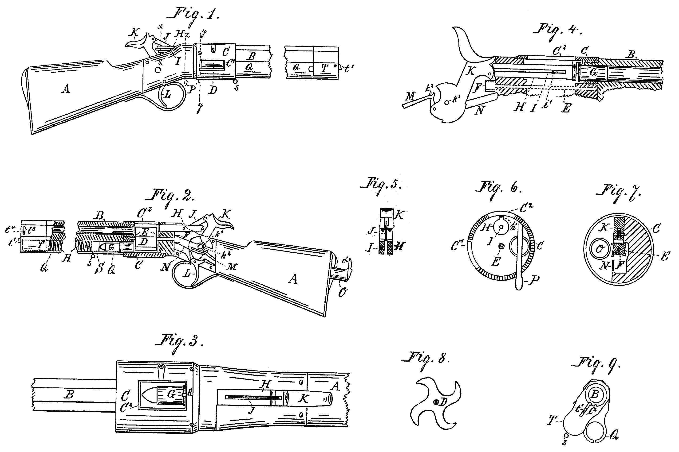
Figure 1 is a side elevation of a gun embodying my invention, showing the hammer and plunger drawn back ready for firing. Fig. 2 is a similar view from the other side, but partly in section. Fig. 3 is a top or plan view of that part of the gun containing the mechanism, the top of the casing being open, showing the cartridge in the position in which it rests just before being forced forward into the barrel. Fig. 4 is a detail sectional view, showing some of the working parts in the position in which they are after the gun is fired, the shell of the exploded cartridge being shown in the barrel. Fig. 5 is a transverse vertical section of the plunger, looking from the dotted line x x in Fig. 1 toward the hammer. Fig. 6 is a similar view of the inside of end of the cylinder, looking toward the stock from the dotted line y y. Fig. 7 is a similar view of the solid part to which the cylinder is joined, looking toward the barrel from the dot ted line z z. Fig. 8 is an end view of the revolving cylinder, as seen from the end next the barrel. Fig. 9 is an elevation of the muzzle of the gun, the movable part of the cartridge-holding tube which is attached to the barrel being shown turned to one side.
In said drawings the various portions are marked with the letters of reference specified in the following description:
A is the stock of the gun. B is the gun barrel. C is a cylindrical casing, which connects the stock to the barrel, and which has one opening, C’, in its side, and another, C^2, on its top, the former being necessary to the working of the gun, and, preferably, left entirely open, while the latter is only for convenience and is, preferably, provided with a door.
D is a revolving cylinder of peculiar construction. Instead of the cartridge-holding spaces being in the form of a semicircle, as has heretofore been the case in cylinders of this kind, one side is rounded off, while the other is brought around to a point, as shown in Fig. 8. By this construction it is enabled to carry the cartridges more securely and With less friction than has heretofore been done. Said cylinder is contained in the casing C, which receives the cartridges from the cartridge-holding tubes, carries them around in line with the barrel, and, after they are fired, receives the shells and discharges them through the opening C’ in the casing C. This cylinder is rigidly mounted on the shaft E, and is rotated by suitable mechanism operating upon the ratchet F on the rear end of said shaft.
The cartridges G, after having been brought into proper position by the cylinder D, are forced forward into the barrel by the plunger H, which is attached to the hammer K by the connecting-rod J, and is actuated thereby.
Upon the end of the plunger H is the hook h’, which projects over and catches the rims of the cartridges, and, as the hammer is drawn back after the gun is fired, withdraws the empty shell from the barrel into the cylinder.
Located in the plunger H is the firing-pin I, which is also operated upon by the hammer F. The said firing-pin slides loosely in a slot formed in said plunger for its reception, and, consequently, when the plunger begins to push a cartridge forward the said firing-pin is thrown back and projects slightly from the rear end of the plunger, as shown, until the hammer comes fully down and the cartridge is pushed fully into the barrel, as shown in Fig. 4. Simultaneously with the completion of its downward movement the hammer strikes the firing pin, driving it into and exploding the cartridge; but as soon as the hammer is started on its return movement the pin is released and is ready for the next cartridge.
The hammer K is operated by the trigger L. and the mainspring Min the ordinary manner. Upon the same pivot, k’, with the hammer K. is the lever N, which is operated by the pin k^2 (against which the mainspring rests and through which it operates) as the hammer is drawn back to turn the ratchet F and with it the cylinder. This ratchet is nearly square, and when the hammer is down it rests upon it, as shown in Fig. 7, and holds it securely locked. In raising the hammer the pin k^2 does not operate the lever N until the plunger is entirely withdrawn from the cylinder. The movement imparted to the ratchet and cylinder by this lever is very quick, which is essential to the perfect Working of a gun of this description. Any other revolving mechanism might be used which answers this requirement.
The cartridge-holding tube O, which is located in the stock of the gun, is not dissimilar to those in ordinary repeating-guns, except that there is a slide, P, which stops the flow of cartridges from this tube while they are being used from the other tube, O, attached to the barrel. The tube Q has a peculiar means of being loaded. The spring R therein being drawn up into the top part, T, the latter is turned part around, as shown in Fig. 9, and the tube is filled with cartridges. When this is done the part T is moved back to its ordinary position, and the spring R, then Operates to force the cartridges into the cylinder D as the latter revolves. The top Tis held in place by the snap or catch t’, which engages in the notch t° in the end of the barrel B. In one side of the part T is a short transverse slot, t^3, through which a pin, t^4 side of the barrel. This slot and pin serve the double purpose of holding the part T on and preventing it from turning too far, which it would otherwise do, and allow the spring to escape from the tube. Two or more of these tubes O may be attached to the barrel, if desired, and the capacity of the gun increased accordingly, by making the cylinder D with a correspondingly greater number of compartments.
When it is not desired to fill the tubes with cartridges the gun can be used as a non-repeating gun by inserting the cartridges, one at a time, through the opening C^2 in the top of the casing C. The shells, however, will be withdrawn and discharged in the same way as When the cartridges are fed from the tubes in the ordinary manner.
Having thus fully described my said invention, what I claim as new, and desire to secure by Letters Patent, is—
1. In a repeating-gun, the open-sided revolving cylinder D constructed with the curved extensions or arms, as shown in Fig. 8, and operating Substantially as specified.
2. The lever N, pivoted on the hammer-pin k’, and having a rearward spring-extension to engage with the mainspring or its link at k^2, in combination with the ratchet wheel or pinion of a revolver-cylinder, substantially as shown and set forth.
In witness whereof I have hereunto set my hand and seal, at Indianapolis, Indiana, this 15th day of January, A. D. 1879.
FERNANDO Y. SUNDERLAND. [L. S]
In Presence Of-
C. Bradford,
Jno. W. Baird.