
US 223100
UNITED STATES PATENT OFFICE.
WILLIAM H. BELL OF BALTIMORE, MARYLAND.
IMPROVEMENT IN CARTRIDGE-HOLDERS.
Specification forming part of Letters Patent No. 223,100, dated December 30, 1879; application filed October 9, 1879.
To all whom it may concern:
Be it known that I, William E. Bell, of Baltimore, in the county of Baltimore and State of Maryland, have invented certain new and useful Improvements in Cartridge-Holders; and I do hereby declare that the following is a full and exact description thereof, reference being had to the accompanying drawings, making a part of this specification.
My invention relates to a novel device for facilitating the charging of the chambers of a revolver or other fire-arm having more than one chamber.
In the use of the ordinary revolver, especially by mounted military, one of the greatest evils connected with the present mode of using the ammunition lies in the difficulty, while in action, of successfully loading the weapon, owing to the necessity of loading each chamber successively, which requires a very considerable time, and not unfrequently results in the Soldier falling in the rear to load, or else abandoning the use of the weapon.
My invention has for its object to avoid these evils, and to provide a means for expeditiously and simultaneously loading all the chambers of the weapon; and with these ends in view my invention consists, first, of a wood, metal, or other holder adapted to receive and hold a series of cartridges by the flanges there of when in a given position, and to release the same by turning said holder, as will be presently explained; and, second, of a cartridge-holder with a given number of cartridges contained therein by the flanges thereof, in ready and compact form, substantially as and for the purposes hereinafter more fully set forth.
In Order that those skilled may fully under stand my invention, I will proceed to describe the construction and operation of the same, referring by letters to the accompanying drawings, in which—
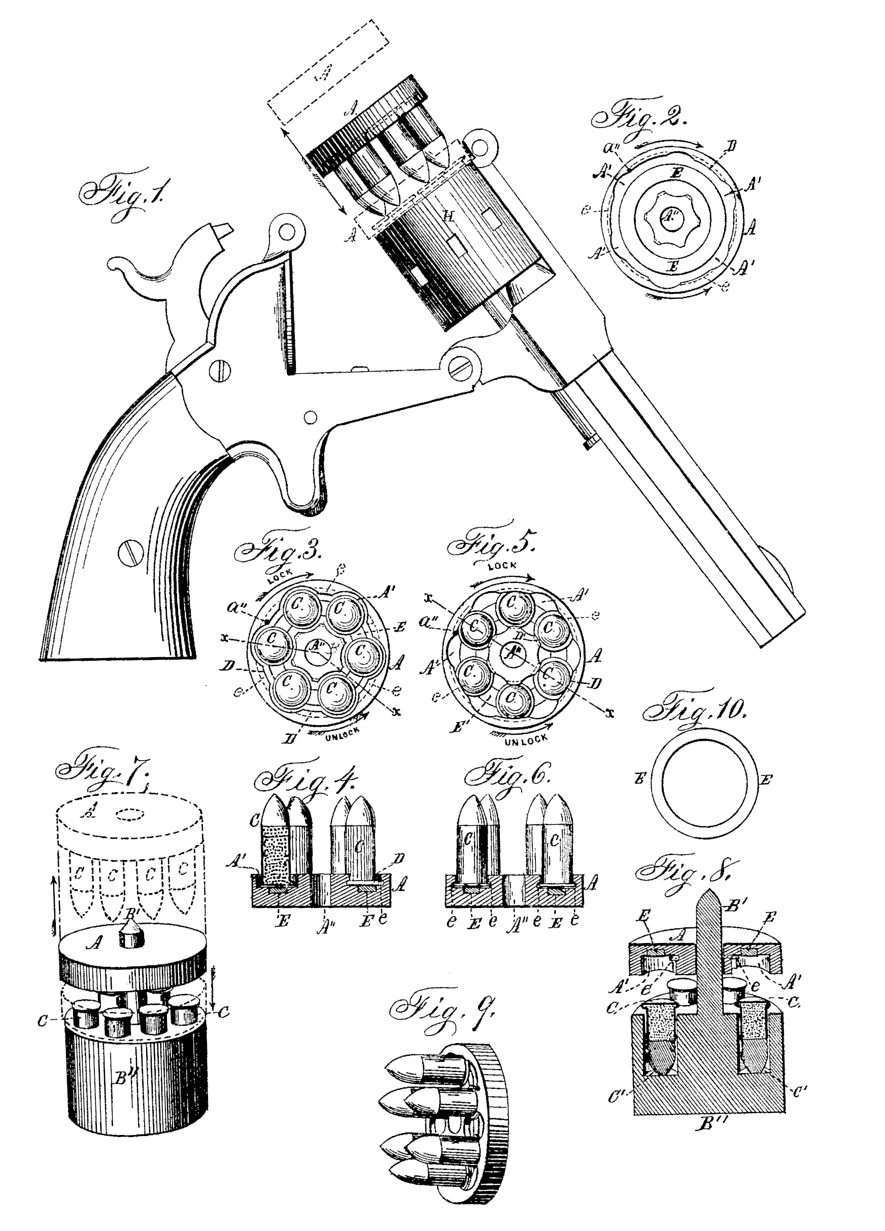
Figure 1 is a side view of a revolver with the barrel tipped to elevate the breech of the cylinder, the dotted lines and arrows indicating the movement necessary to deposit the shells and withdraw the holder. Fig. 2 is a plan view of the inside face of the holder with the cartridges removed; Fig. 3, a similar view with the cartridges in the position necessary to withdraw the holder; Fig. 4, a section at the line x x of Fig. 3; Fig. 5, a similar view to Fig. 3, but with the shells or cartridges locked in position; Fig. 6, a section at the line x x of Fig. 5. Fig. 7 is a perspective view of the holder and the device for charging it; Fig. 8, a central vertical section of the same; Fig. 9, a perspective view of the holder with a full complement of shells locked in position, and Fig. 10 a plan view of a spring or friction ring located in the holder and designed to steady the shells within the holder.
Similar letters indicate like parts in the several figures.
A is my improved holder, which is a block preferably round, and made of wood or any other suitable material. One face of this block is channeled or grooved out at D, leaving a central hub, B, and concentric outer rim, F, the original height of the block. This hub and rim are then cut away to form seats A’, equal in dimensions and conforming in design to the flanged head of the shells C intended to be held therein, and equal in number and relation to the chambers of the weapon for which they are intended, and the intermediate projecting portions of the said hub and rim are grooved and channeled laterally underneath, as shown by dotted lines in Figs. 2, 3, and 5, and designated by the letter e, the distance between the grooves in the hub and rim being equal to the diameter of the flanged head of the shell.
In the bottom of the channel, between the hub and rim, there is arranged in an annular seat or groove a rubber ring, E, or other suit able spring or frictional device for holding the flange of the shell tightly against the up per side of the flange-channel e. a” are stops, arranged at the corners of one or more of the projecting portions of the rim F, and serve to arrest the rotation of the holder when it is being turned in the direction indicated by the lock-arrow to lock the cartridges in place. To release the cartridges the holder is rotated in the reverse direction, as indicated by the unlock arrow.
In order to charge the holders A, I employ a charger, B”, Figs. 7 and 8, which is bored or chambered at C in exact conformity with the weapon for which the shells are intended, and of a depth sufficient only to leave the rims or heads of the shells projecting, as clearly shown.
The charger is provided with a central projecting stem, B’, adapted to pass through a central hole, A”, in the holder, so that the seats therein may be readily caused to register with the chambers of the charger.
When the seats A’ of the charger are in register with the heads of the shells C the holder is pressed down, forcing the heads of the shells up into the seats A’, and compressing the rubber ring or other spring device E. The holder is then turned to the left, which, by reason of the shells being held stationary by the charger, brings the rims or flanges of the shells within the concentric grooves e in the rim and hub of the holder, where they are securely held by the spring E and the checks or stops a”.
The axes of the seats A’ bear such relation to the heads of the shells that no one of the latter can move independently sufficiently far to reach its seat and become accidentally released from the holder; or, in other words, the shells, when locked in position, have their rims or flanges so close together that they afford mutual support, and the whole number must be moved to enable any one or all to be released, and this collective movement is prevented by the frictional contact of the heads of the shells with the rubber ring or spring E.
The holders with the cartridges fixed therein in the manner above described may be arranged in any convenient manner within a belt or other cartridge-box; and when occasion demands the loading of a fire-arm for which they are adapted, the arm is “broken” and tilted, as shown at Fig. 1, and the holder with its contained cartridges placed as shown, shoving them into the cylinder E, and turning the holder slightly to the right, which will bring the heads of the shells into line with their seats A’, when, by their own weight or the action of the spring E, they are ejected and forced into the cylinder.
I do not wish to limit myself, in the construction and application of my improved holder, to any particular size, shape, or capacity, as it may be varied in any of these particulars without departing from the spirit of my invention.
What I claim as new, and desire to secure by Letters Patent, is—
1. A cartridge-holder formed with two or more seats for the introduction of the heads of the shells, with intermediate projections and concentric rim-holding grooves e, and provided with a rubber or other spring, E, substantially as and for the purposes set forth.
2. The holder formed with the seats, rim-holding grooves, and spring e, and provided with one or more checks or stops, a”, substantially as and for the purposes described.
Witness my hand and seal this 9th day of October, A. D. 1879.
WILLIAM H. BELL. [L.S.]
In presence of—
Wm. C. McIntire,
Davis E. Castle.