
US 223101
UNITED STATES PATENT OFFICE.
WILLIAM. H. BELL, OF BALTIMORE, MARYLAND.
IMPROVEMENT IN REVOLVING FIRE-ARMS.
s Specification forming part of Letters Patent No. 223,101, dated December 30, 1879; application filed October 23, 1879.
To all whom it may concern:
Be it known that I, William. H. Bell, of Baltimore, in the county of Baltimore and State of Maryland, have invented certain new and useful Improvements in Fire-Arms; and I do hereby declare that the following is a full and exact description thereof, reference being had to the accompanying drawings, making a part of this specification.
My invention relates to certain improvements in devices for automatically ejecting the empty shells from that class of revolving fire-arms in which the cylinder is loaded from the breech.
Prior to my invention many devices and contrivances have been suggested for extracting shells from breech-loading revolvers, some automatic and others by hand. In most of them, however, the whole number of shells are ejected or partially ejected at once and just prior to reloading, and this result is generally accomplished at the time that the arm is broken to reload. Where the spring-plunger is used to successively eject the shells the cylinder must be rotated to bring each chamber into alignment, and it frequently happens. that the explosion of a shell causes the plunger to spring or jump into a chamber, and thus prevent the rotation of the cylinder. There are sundry other devices with which I am familiar, but none, so far as I am aware, embodying the peculiarity of construction and operation of my improvement, the object of which is to automatically and fully eject each shell an instant of time prior to the discharge of the succeeding one, and through the medium of the main-spring that operates the hammer; and with these ends in view my invention consists of a retractor adapted to take hold of the rim of the shell, and operated by the mainspring through the medium of the hammer during the descent of the same, as will be hereinafter more fully set forth.
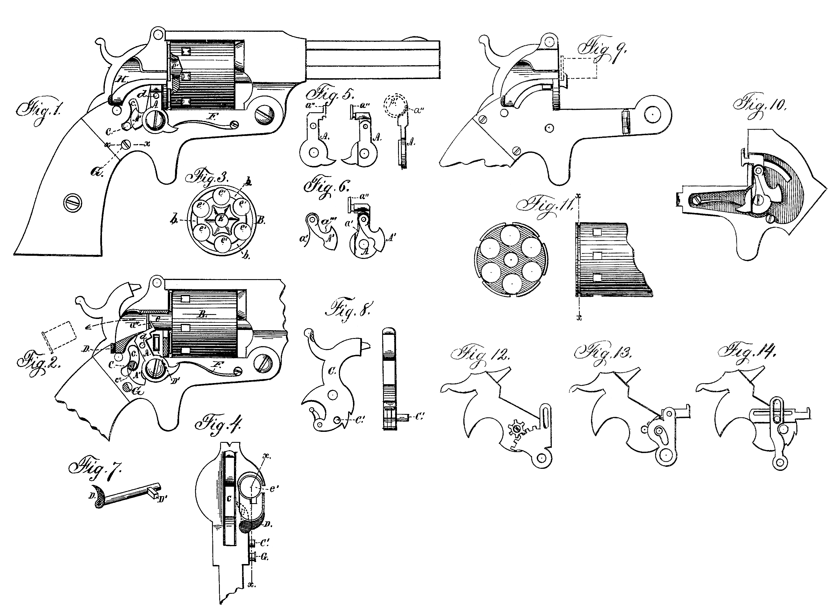
In order that those skilled may fully understand the construction and operation of my improved retractor, I will proceed to describe the same more in detail, referring by letters to the accompanying drawings, in which—
Figure 1 is a side elevation of a revolver with my improved retractor secured in position on the outside; Fig. 2, a similar view, with the guard broken away to expose the retractor in the act of ejecting shell, and with the pin on the hammer in section; Fig. 3, a rear view of the cylinder, showing one form of a groove or channel in which the hook end of the retractor moves; Fig. 4, a rear-view of the revolver, showing the means for rendering the retractor inoperative when desired; Fig. 5, detail views of the retractor without any pawl or click; Fig. 6, a side view of the pawl or click and the same attached to the retractor. Fig. 7 is a perspective view of the rock-shaft and thumb-piece by means of which the retractor is rendered inoperative when desired. Fig. 8 is a side and rear view of the hammer, showing the pin by means of which the retractor is operated; Fig. 9, a side elevation of the rear portion of a revolver with my improved retractor arranged inside; Fig. 10, an inside view of the side plate with retractor secured in position; Fig. 11, a rear sectional and side elevation of a cylinder with a modified form of groove or channel for the hook of the retractor to travel in, and Figs. 12, 13, and 14 side views of modifications of means for vibrating the retractor.
Similar letters indicate like parts in the several figures.
A is the retractor, which may be struck up or formed from a single piece, with its upper end terminating in a hook, a”, adapted to engage the rim of the shell. This retractor is pivoted, by a screw or otherwise, to the side plate of the lock-frame. A pawl, A’,is arranged between the retractor A and the said side plate, being pivoted near the top to the retractor, as clearly shown, and is furnished with a spring, a’, the free end of which lies within a groove or under a shoulder in the upper end of the retractor, so that it shall act to throw the pawl rearward, as seen at Fig. 6.
The lower portion of the retractor, below its center of motion, is projected forward to form a bearing for the end of a spring, F, which throws the hook end of the retractor into its groove in the rear end of the cylinder as soon as the pawl A’ is released.
When arranged on the outside, as shown at Figs, 1 and 2, the lock-plate is cut through, forming a segmental channel, c, through which projects a pin or arm, C, arranged on the side of the hammer, as clearly shown, which pin or arm is designed to take hold of the hook or shoulder formed in the upper edge of the lower end of the pawl A’, to pull the same down until it is released by having its lower curved edge come in contact with a tripping screw or pin, G, one side of which is beveled or cut away, as seen in cross-section at Fig. 2, so that by turning or adjusting said screw it may be made to trip the pawl A’ at variable periods of time, which may be deemed necessary. The pin C is beveled, as seen at c”, to aid in tripping the pawl.
D is a thumb piece or lever on the rear end of a rock-shaft, having a radial arm, D’, at or near its forward end. This rock-shaft is arranged longitudinally under the retractor, inside the lock frame, which is cut or slotted to permit the ejectment of the arm D’, which is so located that when the retractor is pulled sufficiently far back to be out of the way of the cylinder the arm D’ may be forced out in front of the retractor, and hold it in an inoperative position, so that the cylinder B may be charged and the shells exploded without using the retractor, if so desired.
e represents the shells, and e’ the chambers, of the cylinder, between which is formed a series of connecting grooves or channels, b, in which the hook a” of the retractor travels, as seen at Fig. 3, or which may be formed with a continuous groove surrounding the cylinder, as shown at Fig. 11.
E is the central hole and shaft, by which the chambers are secured in position in the usual manner.
H is a channel or groove through which the shells are ejected, and through which they may be forced into position in loading. This channel is preferably slightly turned outwardly at its rear end, to deflect the shells to one side as they are thrown out by the ejector; and I is a guard.
The pin C on the face of the hammer may be so arranged, when the retractor is placed on the inside of the lock-frame, as to move in and out to catch into its seat in the pawl A’; or the pawl and retractor may be arranged in any of the ways shown at Figs. 12, 13, and 14, though I prefer the arrangement shown at Figs. 1 and 2 or at Fig. 10.
Having described the construction and arrangement of my improved retractor, I will now explain its operation.
Suppose the cylinder fully charged and the weapon ready for use, as seen at Fig. 1. The hammer is drawn back and the lever D turned up, throwing out the arm D’ on the rock-shaft to hold the retractor inactive. The trigger is pulled and cartridge No. 1 is exploded. The hammer is raised again, rotating the cylinder, to bring another chamber in alignment and the exploded chamber in front of the retractor. The lever D is now turned down, and the hook a”, by the action of the spring F, is thrown into the groove b in the cylinder, and travels behind the rim of the exploded shell just previous to the descent of the hammer. As the hammer descends the pin C, acting in the shoulder or notch a”‘ in the pawl A’, pulls the retractor back, and its hook a” draws the exploded shell from its chamber and ejects it just before the point of the hammer strikes the next shell, just previous to which time, also, the trip G has released the pawl, and the hook a” flies back into the groove b, so that as the cylinder is rotated by again raising the hammer the next exploded shell is carried around, so as to overlie the said hook.
The raising of the hammer each time, it will be observed, brings the pin C into position within the shoulder in the pawl. The motions are so timed that the hammer obtains a slight momentum before the pin C begins to pull on the pawl A’.
From the foregoing it will be seen that I employ the force of the mainspring to retract the exploded shells, and that they are retracted an instant of time prior to the explosion of the next succeeding one, so that by no accident can an exploded shell be left remaining in a chamber to become corroded therein.
The retractor may be provided with a knob, d, or other suitable device, by which it may d, or other suitable device, by which it may cocking the weapon.
What I claim as new, and desire to secure by Letters Patent, is—
1. In combination with the vibratory retractor A, the rock-shaft provided with the lever D and radial arm D’, arranged, as described, to hold the retractor inoperative, as set forth.
2. The retractor A and pawl A’, pivoted together, and the latter pivoted to the frame, as described, in combination with the spring F, for throwing the hook end of the retractor in position, and the pin C on the hammer, adapted to vibrate the retractor during the descent of the hammer, substantially as and for the purpose set forth.
3. In combination with the extractor A and the pawl A’, formed with the shoulder or notch a”‘ and curved lower portion, the pin C and trip device G, constructed as described, and , for the purpose set forth.
Witness my hand and seal.
WILLIAM H. BELL. [L. S.]
In presence of—
Wm. C. McIntire,
F. W. Smith, Jr.