
US 116422
UNITED STATES PATENT OFFICE.
SULLIVAN FOREHAND AND HENRY C. WADSWORTH, OF WORCESTER, MASS.
IMPROVEMENT IN REVOLVING FIRE-ARMS.
Specification forming part of Letters Patent No. 116,422, dated June 27, 1871.
To all whom it may concern:
Be it known that we, Sullivan Forehand and Henry C. Wadsworth, both of the city and county of Worcester and State of Massachusetts, have invented certain new and useful Improvements in Revolving Fire-Arms; and we do hereby declare that the following is, a full, clear, and exact description of the same, reference being had to the accompanying drawing which forms a part of this specification, in which—
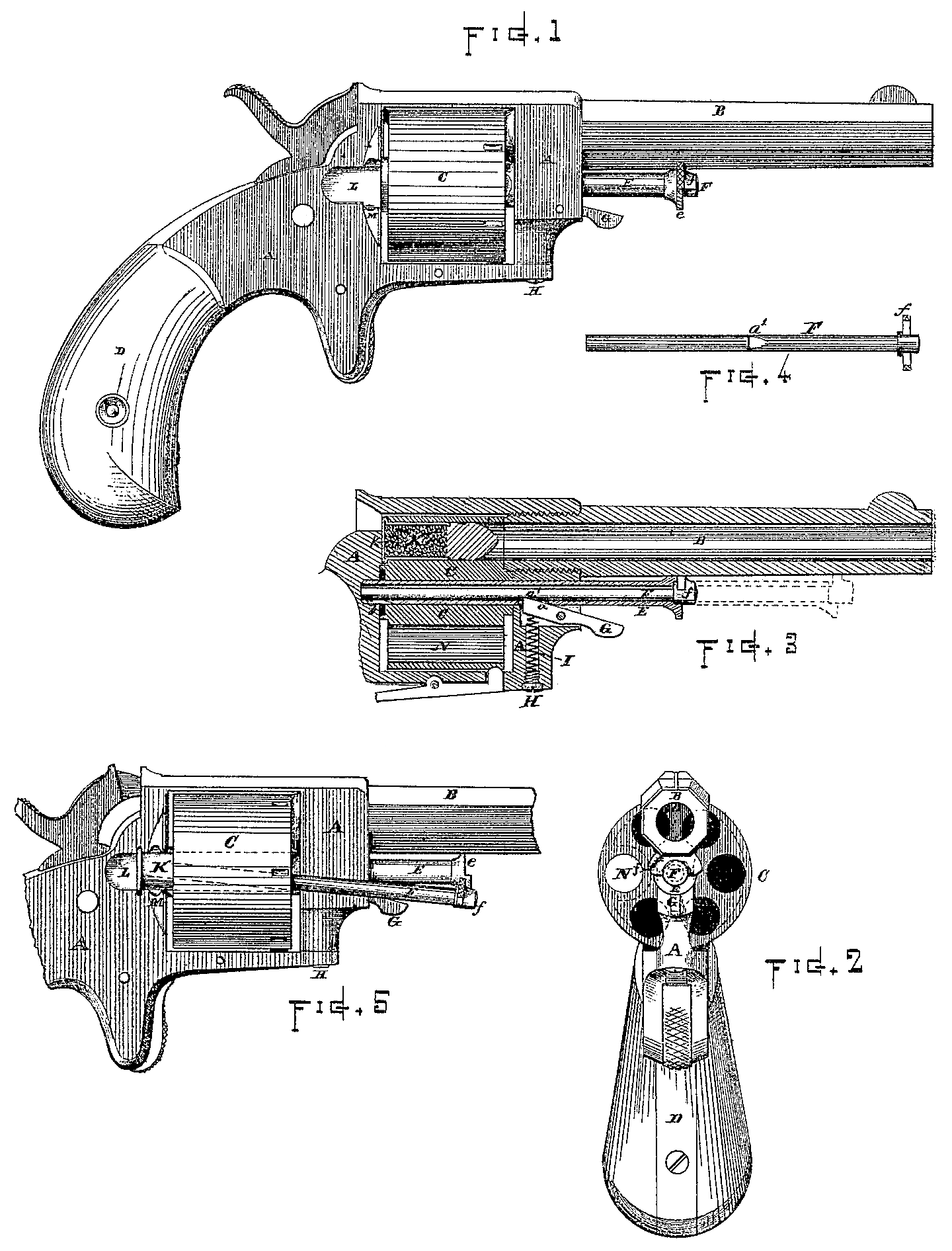
Figure 1 represents a side view of a revolving pistol with our improvements applied thereto. Fig.2 represents a front view of the same. Fig. 3 represents a central longitudinal section of the barrel, cylinder, and parts adjacent thereto. Fig 4 represents a view of the removable cartridge shell discharging-pin, and Fig. 5 represents a side view of a portion of the arm, illustrating the manner of using the discharging-pin.
To enable others skilled in the art to make and use our improvements in revolving fire-arms, we will describe it more in detail.
The nature of our invention consists in the combination, with the base-pin, of a revolving cartridge-shell discharging-pin, as hereinafter described.
In the drawing the part marked A indicates the frame of the fire-arm. B indicates the barrel; C, the cylinder; and D, the stock, which parts may C, the cylinder; and D, the stock, which parts may forms to suit the size and purpose of the arm. E indicates the base-pin, upon which the cylinder revolves. Said pin is supported in the frame A at the ends of the cylinder, and is formed hollow throughout its length to receive a removable cartridge-shell discharging-pin, F, which latter is inserted through its center in the manner illustrated in Fig. 3. A catch-lever, G, is arranged in the forward part of the frame A for retaining the pins E and F in place. The end of said catch-lever G locks into holding-notches formed centrally at the under side of the pins E and F, as shown in Fig. 3, and thus prevents the pins from being drawn out until the end of the lever G is depressed. The holding-notch a upon the base-pin E is cut completely through the metal, and the notch a? upon the pin F is made to correspond there with in position, thus enabling the catch lever G to hold both of the pins E and F with equal security. The catch-lever G is pressed upward, and held into the notch a by means of a small coil-spring, I, arranged in a recess or opening in the frame A, directly beneath the rear end of the lever G; and a screw-top, H, is inserted in the end of the opening to retain the spring I in position. The head e of the base-pin E is formed straight at its upper side, and fits against the under side of the barrel B, thus preventing any rotary, movement which the pin might otherwise acquire from the friction of the revolving cylinder. The removable cartridge-shell discharging-pin F is prevented from turning by means of its flanged head f, which is fitted to the form of the barrel B, as shown. The heads e and f also serve as guides when restoring the pins to position after they have been withdrawn. By slightly pressing upon the catch-lever G the pin F can be withdrawn to be used in forcing the cartridge-shells K from the cylinder after the charges have been fired, while the base-pin E is left remaining in position to support the cylinder during such operation. The cylinder C can be removed from the frame A, for cleaning or any other purpose, by pressing up the catch-lever G sufficiently to release its end from the holding-notch a in the base-pin E, and by then drawing out both of the pins E and F to the position indicated by dotted lines in Fig. 3 of the drawing, this releases the cylinder, so that it can be slipped out at the side of the frame. A recess, L, is formed in the side of the frame A, and the flange M, at the rear of the cylinder, is cut away, as shown in full lines, Figs. 1 and 5, and dotted lines, Fig. 2, thus allowing sufficient space at that position to insert the cartridge into the chamber N of the cylinder or to force out the empty shell K. This latter operation is performed by the aid of the pin F, which is to be withdrawn from the base-pin E and used in the manner illustrated in Fig. 5. When the pins E and F are in the position indicated by dotted lines, Fig. 3, the catch-lever G locks into a notch, b, formed near the rear end of the pin E, and also presses upon the pin F, whereby said pins are retained in their withdrawn position, and are not liable to drop out or become detached from the frame, and thus inconvenience the person using the arm.
It will readily be observed by those skilled in the manufacture and use of revolving fire-arms that our improvement is of great practical value, inasmuch as the arm can be charged and the empty shells expelled without the inconvenience and trouble of removing the cylinder from the frame, or of the use of complicated and expensive shell-extractors.
A small elliptic spring may, if desired, be attached to the side of the shell-discharging pin F for retaining it within the interior of the base pin E, and the lever G be used simply to hold the base-pin E within the frame; but we prefer the method of construction shown in the drawing.
Having described our improvements in revolving fire-arms, what we claim therein as our invention, and desire to Secure by Letters Patent, is—
1. The combination, with the removable base-pin in a revolving fire-arm, of a removable shell-discharging pin.
2. The combination, with the base-pin E, of the cartridge-shell discharging-pin F and spring catch-lever G, substantially as and for the purposes set forth.
SULEVAN FOREHAND
HENRY C. WADSWORTH.
Witnesses:
Thos. H. Dodge,
Chas. H. Burleigh.