
US 116078
UNITED STATES PATENT OFFICE.
JOHN L. MOSS AND EDWARD W. JOHNSON, OF COLUMBUS, MISSISSIPPI.
IMPROVEMENT IN REVOLVING FIRE-ARMS.
Specification forming part of Letters Patent No. 116,078, dated June 20, 1871.
To all whom it may concern:
Be it known that we, John L. Moss and Edward W. Johnson, of Columbus, in the county of Lowndes and State of Mississippi, have invented a new and useful Improvement in Revolving Fire-Arms; and we do hereby declare that the following is a full, clear, and exact description thereof, which will enable others skilled in the art to make and use the same, reference being had to the accompanying drawing forming part of this specification, in which—
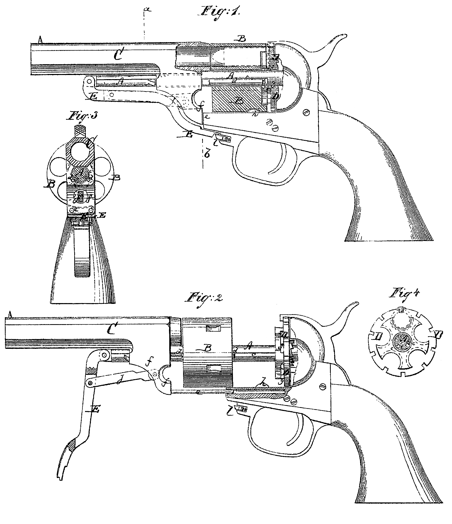
Figure 1 represents a side view, partly in section, of our improvement in fire-arms, showing the parts in position after firing. Fig. 2 is a side view, partly in section, of the same, showing the barrel drawn forward for loading. Fig. 3 is a transverse section of the same on the line a b, Fig. 1. Fig. 4 is a detail face view of the rotating breech-piece.
Similar letters of reference indicate corresponding parts.
This invention has for its object to facilitate the loading and shell-extracting process in revolving rifles and pistols; and consists, principally, in the use of a rotary breech-plate, which is hung upon the base-pin, so that it will revolve but not slide thereon, while the cylinder can freely slide, being, by keys, connected With the barrel. The breech-plate has grooved supports for the cartridge-head, and will retain the shells when the cylinder is carried forward, extracting them from the latter.
A in the drawing represents the base-pin of the fire-arm, secured to the stock in the ordinary manner. It has one or more longitudinal grooves, c c. B is the cylinder. C is the barrel of the arm. The cylinder is fitted upon the base-pin, so that it can freely revolve thereon, but also so that it can slide, for which latter purpose headed keys d are fitted into the grooves c, so that their heads are in contact with the ends of the cylinder. The barrel C. is locked to the cylinder by the same keys d, or their extensions, so that it will slide in conjunction with the same. The barrel is guided, during its longitudinal motion, by two pins, e e, which extend backward from its lower projection f into the lower part of the stock. These pins e slide out with the barrel, as shown in Fig. 2, and prevent the turning or lateral displacement of the barrel without interfering with the free rotation of the cylinder. Upon the breech end of the base-pin is hung a plate, D, which can freely revolve, but not be longitudinally displaced. It is, by the ordinary ratchet apparatus, connected with the lock to receive intermittent rotary motion by the movements of the hammer. The plate D has in its face semicircular recesses, which serve as supports for the cartridge-heads, and have grooves g g, to receive the flanges of the cartridge shells.
The arm is loaded when the cylinder is drawn forward, as in Fig. 2, when the cartridges can be successively attached to the plate D by being fitted into the grooved recesses of the same. The cylinder is then pushed back and locked by the ordinary lower catch l. It can now freely revolve with the plate D, so as to bring the cartridges successively inline with the barrel, and explode the same by the hammer. When, after a discharge, the cylinder is again moved forward, the cartridge-shells will be retained by the plate D, which has hold of their flanges; they will thereby be extracted from the cylinder. The shells are easily removed from the plate D, which can be recharged, as aforesaid. The longitudinal movement is advantageously obtained by means of a lever, E, pivoted to the end of the base-pin, and connected, by a link, j, with the barrel. Its end can be locked to the frame of the fire-arm, when the parts are in position for firing, by a spring catch, l, as in Fig. 1.
Having thus described our invention, we claim as new and desire to secure by Letters Patent—
1. The breech-plate D, provided with the grooved recesses to constitute a holder of cartridges and shell-extractor, as set forth.
2. The sliding cylinder B, combined with the rotary breech-plate D, substantially as herein shown and described.
3. The barrel C, connected and combined with the rotating reciprocating cylinder B, substantially in the manner herein shown, so that it can slide together with the same, as specified.
4. The guide-pins e e, combined with the sliding barrel C and the frame, substantially as herein shown and described, for the purpose specified.
5. The lever E and link j, combined with the sliding barrel and cylinder to operate the same, as set forth.
6. The base-pin A, grooved lengthwise, combined with the headed keys d, whereby the sliding and also rotating motion of the cylinder is obtained, as specified.
JOHN L, MOSS.
EDWARD W. JOHNSON.
Witnesses:
H. C. Goodrich,
J. H. Delany.