
British 1622
Revolving or Repeating Fire-arms.
LETTERS PATENT to Francis Alexandre Le Mat, of New Orleans, in the State of Louisiana, in the United States of America, Colonel Aide-de-Camp, for the Invention of “ Improvements in the Construction of Revolving or Repeating Fire-arms.”
Sealed the 4th January 1860, and dated the 8th July 1859.
PROVISIONAL SPECIFICATION left by the said Fran§ois Alexandre Le
Mat at the Office of the Commissioners of Patents, with his Petition, on the 8th July 1859.
I, Francois Alexandre Le Mat, of New Orleans, in the State of Louisiana, in the United States of America, Colonel Aide-de-Camp, do hereby declare the nature of the said Invention for “ Improvements ur the Construction op Revolving or Repeating Fire-arms/* to be as follows:—
My Invention of improvements in the construction of revolving or repeating fire-arms consists in a novel construction or arrangement of parts whereby a repeating fire-arm, such as pistol or rifle revolvers, may be rendered more convenient and effective weapons than heretofore, without adding to the weight or to the complication of the parts.
My Invention relates to that description of repeating fire-arm in which a moveable breech piece pierced for several charges is made to rotate on its spindle, in order to bring every charge in succession under the hammer, and opposite to a common barrel through which every such charge is made to pass.
My Invention consists principally in mounting such rotating breech on a hollow central spindle or barrel, which will form an additional barrel for the arm, and which additional barrel I prefer to charge wbth a cartridge containing a number of small bullets instead of a single bullet. This central barrel or hollow spindle may be charged either at the muzzle or the breech, and the move-able breech is made to rotate thereon in any well-known or other convenient manner. Every barrel of the rotating breech must of course be provided with a nipple and touch-hole, and the central barrel must be also so provided. The same trigger and hammer is used for rotating the moveable breech, and for discharging the primers of the same, and also the primer of the central barrel or hollow spindle. As, however, the nipples of the rotating breech-piece and of the central barrel or spindle are not in the same circuit, the head of the hammer is made moveable, and is jointed so that by the finger or thumb of the hand which holds the pistol, the moveable part of the hammer head may be moved up or down in order to bring the hammer into a position suitable for discharging the primers of the rotating breech or of the central barrel, as may be required. This moveable head of the hammer is also connected by a spring or small lever placed inside the hammer wbth the mechanism of the lock, whereby the moveable breech is rotated, and is so arranged that when the moveable head is pushed back so as to act on the nipple of the central barrel, the small spring or lever in connection with the hammer will throw the rotating mechanism out of gear with the moveable breech, which will consequently remain stationary until the head of the hammer is returned to its original or normal state.
Another improvement in the hammer consists in forming two small projecting wings at the side of the head of the hammer for the purpose of fitting against a projecting part of the rotating breech, and locking the same, thereby preventing the latter from rotating when the hammer is let down on to such projecting part. The rammer for pushing the charge into the barrel is worked by a jointed lever, and in order to ensure its proper action and accurate working, the rammer is made to work on a fixed guide piece attached to a convenient part of the metal frame of the arm. Part of the lever of the hammer is made removeable, so that it may be used for the purpose of loading the central barrel. This removeable part of the lever is also fitted in such a manner as to admit of a screw being fixed thereon for withdrawing a charge when required.
SPECIFICATION in pursuance of the conditions of the Letters Patent, filed by the said Francois Alexandre Le Mat in the Great Seal Patent Office on the 7th January 1860.
TO ALL TO WHOM THESE PRESENTS SHALL COME, I, Francois Alexandre Le Mat, of New Orleans, in the State of Louisiana, in the United States of America, Colonel Aido-dc-Camp, send greeting.
WHEREAS Her most Excellent Majesty Queen Victoria, by Her Letters Patent, bearing date the Eighth day of July, in the year of our Lord One thousand eight hundred and tifty-nine, in the twenty-third year of Her reign, did, for Herself, Her heirs and successors, give and grant unto me, the said Francois Alexandre Le Mat, Her special license that I, the said Francois Alexandre Le Mat, my executors, administrators, and assigns, or such others as I, the said Francois Alexandre Le Mat, my executors, administrators, and assigns, should at any time agree with, and no others, from time to time and at all times thereafter during the term therein expressed, should and lawfully might make, use, exercise, and vend, within the United Kingdom of Great Britain and Ireland, the Channel Islands, and Isle of Man, an Inven-: tion for “ Improvements in the Construction of Revolving or Repeating Firearms,” upon the condition (amongst others) that I, the said Francois Alexandre Le Mat, by an instrument in writing under my hand and seal, should particularly describe and ascertain the nature of the said Invention, and in what manner the same was to be performed, and cause the same to be filed in the Great Seal Patent Office within six calendar months next and immediately after the date of the said Letters Patent.
NOW KNOW YE, that I, the said Francois Alexandre Le Mat, do hereby declare the nature of my said Invention, and in what manner the same is to be performed, to be particularly described and ascertained in and by tho following statement, reference being had to the Drawing hereunto annexed, and to the letters and figures marked thereon (that is to say):—
My Invention of “Improvements in the Construction of Revolving or Repeating Fire-arms,’* consists in a novel construction or arrangement of parts whereby a repeating fire-arm, such as a pistol or rifle revolver, maybe rendered a more convenient and effective weapon than heretofore, without adding to the weight or to the complication of the parts.
My Invention relates to that description of repeating fire-arm in which a moveable breach piece pierced for several charges is made to rotate on a central spindle, in order to bring every charge in succession under the hammer and opposite to a common barrel through which every such charge is mode to pass.
My Invention consists principally in mounting such rotating breech on a hollow central spindle or barrel which will form an additional barrel for the arm, and which additional barrel I prefer to charge with a cartridge containing a number of small bullets instead of a single bullet. This central barrel or hollow spindle may be charged either at the muzzle or the breech, and the moveable breech is made to rotate in any of the well-known ways or other convenient manner. Every barrel of the rotating breech must of course be provided with a nipple and touch hole, and the central barrel must be also so provided. The same trigger and hammer is used for rotating the moveable breech and for discharging the primers of the same, and also the primer of the central barrel or hollow spindle. As, however, the nipples of the rotating breech piece and of the central barrel or spindle are not in the same circuit, the head of the hammer is made moveable, and is jointed so that by the finger or thumb of the hand which bolds the pistol, the moveable part of the hammer head may be moved up or down in order to bring the hammer into a position suitable for discharging the primers of the rotating breech or of the central barrel, as may be required. This moveable head of the hammer is also connected by a spring or small lever placed inside the hammer with the mechanism of the lock whereby the moveable breech is rotated, and is so arranged that when the moveable head is pushed back so as to act on the nipple of the central barrel, the small spring or lever in connection with the hammer will throw the rotating mechanism out of gear with the moveable breech, which will consequently remain stationary until the head of the hammer is returned to its original or normal state.
Another improvement in the hammer consists in forming two small projecting wings at the side of the head of the hammer for the purpose of fitting against a projecting part of the rotating breech and locking the same, thereby preventing the latter from rotating when the hammer is let down on to such projecting part. The rammer for pushing the charge into the barrel is worked by a jointed lever, and in order to insure its proper action and accurate working, the rammer is made to work on a fixed guide piece attached to a convenient part of the metal frame of the arm. Part of the lever of the rammer is made removeable, so that it may be used for the purpose of loading the central barrel. This removeable part of the lever is also fitted in such a manner as to admit of a screw being fixed thereon for withdrawing a charge when required.
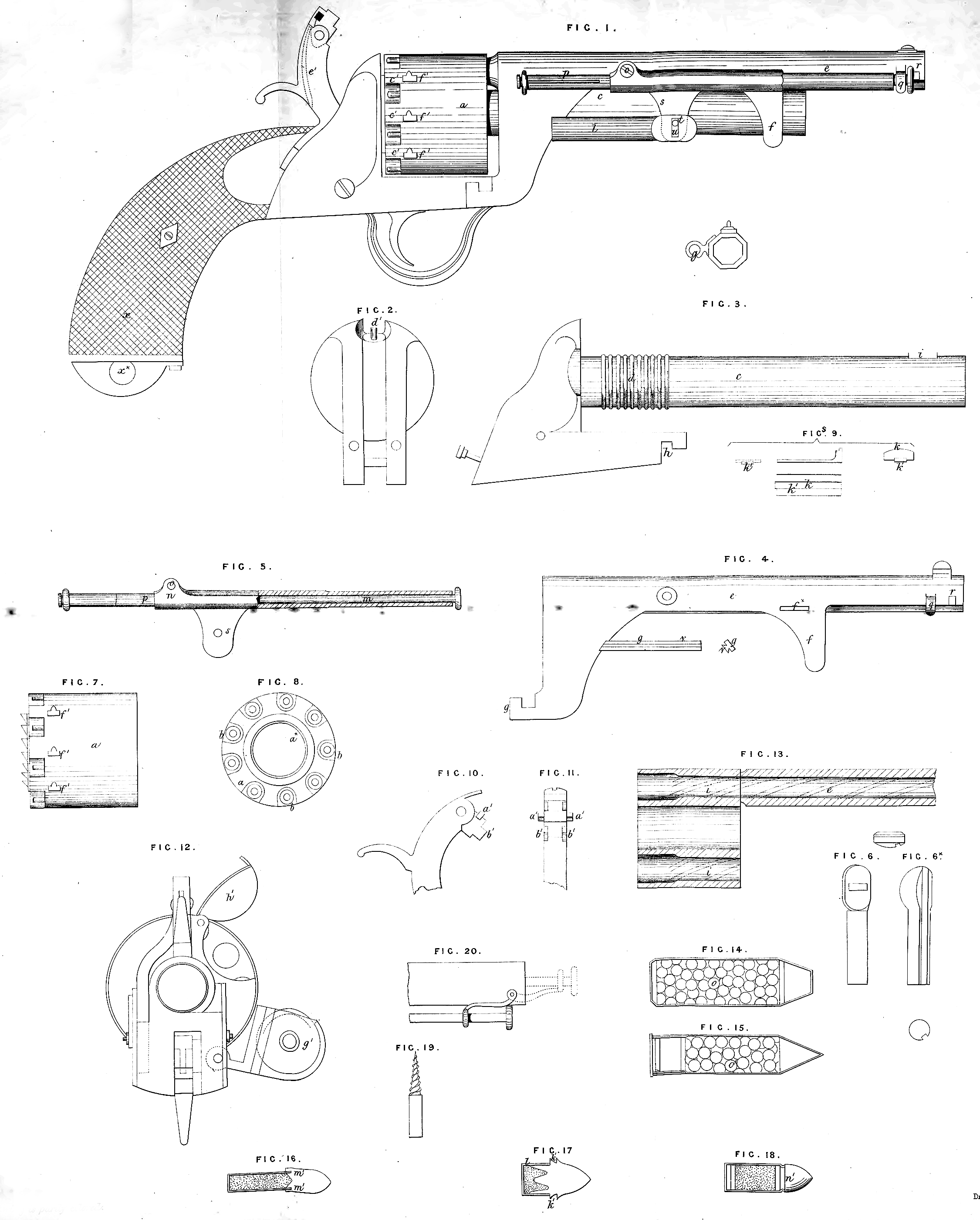
In the accompanying Drawing I have shewn various views of a pistol constructed according to my improvements, some of the parts being shewn detached in order that their construction and operation may be more clearly seen and understood.
Fig. 1 is an outside view of my improved revolver, taken on that side where the ramrod and its plunger are situate. Figures 2 and 3 are detached views of the central barrel and the parts connected therewith. This central barrel is intended to receive a cartridge or charge containing grape or case shot. Fig. 4 is a detached view of the barrel which is common to ail the chambers. Fig. 5 is a sectional view of the piece, to which are adapted the ramrod and ramming plunger represented at Figures 6 and 6*. Figures 7 and 8 are side and end views of the rotating breech adopted in this improved construction of revolver. Figures 9 shew several views of the key whereby the chamber barrel is attached or secured to the central barrel. Figures 12 and 13 represent in section and end view the arrangement of breech chambers to be applied to breech-loading fire-arms, and Figures 14, 15, 16, 17, and 18 shew various constructions of bullets and cartridges which may be employed with my improved revolver. Fig. 19 represents the screw which is to be adapted to the end of the ramrod for cleaning the barrels, and Fig. 20 represents the mode of fixing the ramrod when it is desired to place it under the central barrel.
My improved revolver consists of a rotating breech a, having nine chambers h. The rotating breech a has a central hole or opening a*, Fig. 8, through which passes the fixed central barrel c, which is of larger diameter or calibre than the surrounding chambers of the moveable breech; this breech is simply slipped on to the central barrel c, the backward extremity of which has ribs, projections, or rings dy like screw threads formed upon it, as shewn in Fig. 3, for the reception of some lubricating material to facilitate the movement of the rotating breech. Above this central barrel c, thus furnished with its breech chambers, is a second barrel