
British 2896
LETTERS PATENT to James Kerr, of 17, Bedford Terrace, Trinity Square, Southwark, in the County of Surrey, Engineer, for the Invention of “ Improvements nr the Construction of Revolving Fire-arms.”
Sealed the 25th February 1859, and dated the 17th December 1858.
PROVISIONAL SPECIFICATION left by the said James Kerr at the Office of the Commissioners of Patents, with his Petition, on the 17th December 1858.
I, James Kerr, of 17, Bedford Terrace, Trinity Square, Southwark, in the County of Surrey, Engineer, do hereby declare the nature of the said Invention for “ Improvements in the Construction op Revolving Fire-arms,” to be as follows:—
This Invention relates to an improved construction and arrangement of that class of fire-arms known as “ revolvers,” whereby greater cheapness, simplicity, and certainty of action is obtained. According to this Invention it is proposed to apply the ordinary gun lock and cock with the usual safety bolt to revolving fire-arms. The lock is pulled off by the trigger blade in the usual manner, but by having an extra “ bent ” in the tumbler, the lock can be snapped and cocked by simply pulling the trigger; for which purpose I use, in conjunction with the extra “ bent ” above referred to, a short lever in the trigger, which is kept in the proper position by a hook formed on its edge and a stud on the top of the tumbler. The chamber is rotated in the ordinary well known manner ; it revolves on a rod or spindle inserted into its place from behind, and is adjusted or tightened up when necessary by an adjusting tube or not tapped into the frame of the pistol, or an adjusting tube may be applied for the same purpose to the base of the cylinder. In order to shield or protect the chambers when charged, from accidental explosion, by coming in contact with any hard body, I propose to form a raised boss or shield on the frame of the arm, which boss will also have the effect of increasing the strength of the frame. The stock or handle is attached by an upper and under strap, the upper one being either secured to or forged in one piece with the frame. The stud or stop which holds the cylinder in its proper position when being fired is made to enter the recesses in the chamber in a horizontal position in place of in a vertical one, as hitherto. The cylinder rod or spindle is held in its place by a stationary stud pin, the end of which enters a groove in the cylinder rod, which groove is made slightly spiral at the back end, so that on partially turning the rod it will not only be released ready for withdrawal, but will be also started slightly, thereby facilitating its removal when necessary. The lever rod has no working fulcrum of its own, but is curved at the heel, and such curved portion works between two fixed stud pins, so that a moving axis is obtained, which axis is the point of junction with the plunger; by this arrangement no pins or slots are required in the lever.
SPECIFICATION in pursuance of the conditions of the Letters Patent filed by the said James Kerr in the Great Seal Patent Office on the 17th June 1859.
TO ALL TO WHOM THESE PBESENTS SHALL COME, I, James Kerr, of 17, Bedford Terrace, Trinity Square, Southwark, in the County of Surrey, Engineer, send greeting.
WHEREAS Her most Excellent Majesty Queen Victoria, by Her Letters Patent, bearing date the Seventeenth day of December, in the year of our Lord One thousand eight hundred and fifty-eight, in the twenty-second year of Her reign, did, for Herself, Her heirs and successors, give and grant unto me, the said James Kerr, Her special license that I, the said James Kerr, my executors, administrators, and assigns, or such others as I, the said James Kerr, my executors, administrators, or assigns, should at any time agree with, and no others, from time to time and at all times thereafter during the term therein expressed, should and lawfully might make, use, exercise, and vend, within the United Kingdom of Great Britain and Ireland, the Channel Islands, and Isle of Man, an Invention for “ Improvements in the Construction op Bevolving Fire-arms,” upon the condition (amongst others) that I, the said James Kerr, by an instrument in writing under my hand and seal, should particularly describe and ascertain the nature of the said Invention, and in what manner the same was to be performed, and cause the same to be filed in the Great Seal Patent Office within six calendar months next and immediately after the date of the said Letters Patent.
NOW KNOW YE, that I, the said James Kerr, do hereby declare the nature of my said Invention, and in what manner the same is to be performed, to be particularly described and ascertained in and by the following statement, reference being had to the accompanying Drawings, and to the letters and figures marked thereon, that is to say :—
My said Invention relates to an improved construction and arrangement of that class of fire-arms known as “revolvers,” whereby greater cheapness, simplicity, and certainty of action is obtained than by the ordinary revolvers at present in use. According to this Invention I am enabled to apply the ordinary gun lock and cock with the usual safety bolt to revolving fire-arms. The lock is pulled off by the trigger blade in the usual manner, but by having an extra “ bent” in the tumbler, the lock can be snapped and cocked by simply pulling the trigger; for which purpose I use, in conjunction with the extra “ bent ” above referred to, a short lever in the trigger, which is kept in the proper position by a hook formed on its edge and a stud on the top of the tumbler. The chamber is rotated in the ordinary well known manner; it revolves on a rod or spindle inserted into its place from behind or from the front, and is adjusted or tightened up when necessary by an adjusting tube or nut tapped into the base of the cylinder. The lever rod has no working fulcrum of its own, but it is curved at the heel, and such curved portion works between two fixed stud pins, so that a moving axis is obtained, which axis is the point of junction with the plunger; by this arrangement no pins or slots are required in the lever.
Such being the nature of my said Invention, I shall now proceed to describe in what manner the same is to be performed by reference to the several Figures on the Sheet of Drawings hereunto annexed, the same letters of reference indicating corresponding parts throughout all the Figures.
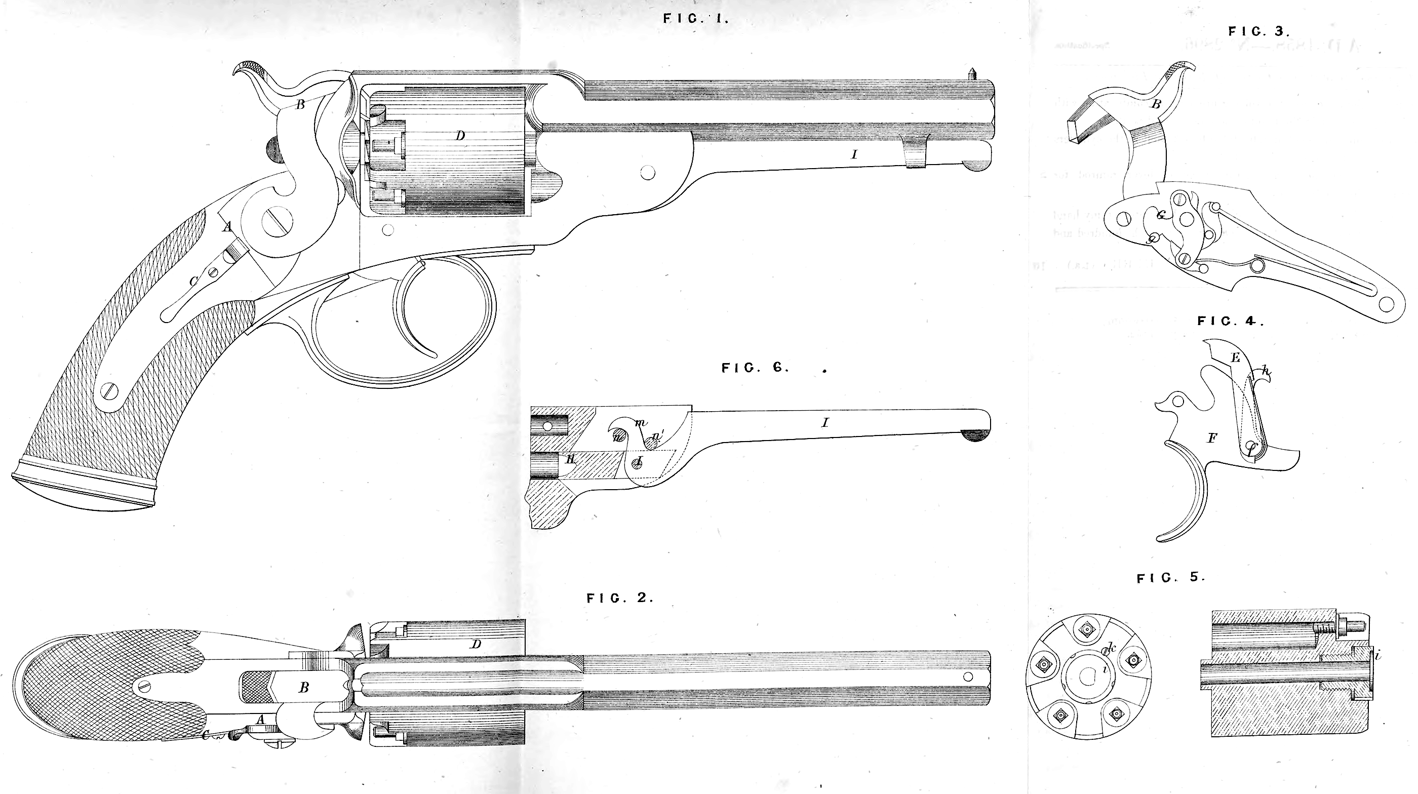
Figure 1 of niy Drawings represents a full-sized side elevation of my improved “ revolver ”complete; Figure 2 is a corresponding plan of the same; Figure 3 is a side elevation of the lock detached, shewing the interior thereof; Figure 4 is a side elevation of the trigger and trigger blade detached, shewing the ordinary lever which actuates the cylinder and the hook which brings the trigger into position when cocking the lock; Figure 5 represents an end elevation and longitudinal section of a cylinder detached, shewing the mode of applying the adjustable base thereto ; and Figure 6 is a sectional detail of a portion of the pistol, shewing my improved lever ramrod.
Figures 1 and 2 of my Drawings shew the application of an ordinary gun or pistol lock A to a revolving fire-arm. By applying an ordinary gun or pistol lock to revolvers greater simplicity and cheapness are obtained, whilst the action being completely inclosed within the stock, the danger of pieces of discharged caps or other matter falling into the lock and deranging its action, as is frequently the case with the ordinary revolver, is entirely obviated. The lock is detached from the body or frame, and the cock B works outside of the lock plate in the ordinary manner. C is the usual safety bolt, in combination with which, however, I propose to use an additional safety bolt, which acts upon the trigger; this latter bolt is made to slide out from the trigger guard, so that it may be readily withdrawn by the finger before firing. The rotation of the charge chamber D is effected by the following means, combined with the ordinary gun lock:—The ordinary lever E (Figure 4) is jointed to the trigger F, which turns on the fixed centre f and the point of this lever acts upon the ratchet teeth formed in the base of the cylinder, wdiich arrangement is common to most revolving fire-arms, and forms no part of my present Invention, except when applied to and combined with the ordinary gun lock, as described and illustrated by my Drawings. A stud g (Figure 3) is formed on or inserted into the side of the tumbler G of the lock ; this stud takes into the hooked link h (shewn in dotted lines in Figure 4), which link is jointed to the trigger by the same pin which serves to secure the lever E. The cocking of the lock w ill obviously cause the stud g to raise the trigger, and consequently the lever E with it, thereby rotating the cylinder, and at the same time lifting a stop bolt or bringing the end of the trigger itself into a recess formed in the cylinder, which locks it in the proper position for discharge. The “ single pulling action,” namely, the power of cocking and firing by simply pulling the trigger, may be easily obtained in this lock by simply having an extra “ bent ” or notch in the tumbler, and a short lever or lifting sear attached to the trigger, the end of which lever takes into the extra “bent” during its upward movement so as to cock the lock, and is then thrown off or released from the “ bent,” when the cock will fall and discharge the arm. This is a well known arrangement for obtaining the single pulling action.
Figure 5 illustrates the mode I adopt for adjusting the cylinder so as to maintain it in close proximity to the breech of the barrel. In practice it is found that the cylinders or charge chambers of revolving fire-arms are liable to end play in the frame, in which case, by reason of the cylinder no longer fitting close against the breech of the barrel, an escape of the gases ensues, and the efficiency of the arm is consequently much impaired. To remedy this defect in a simple and effective manner, I propose to insert into the base of the cylinder an adjustable screwed plug of hardened steel, as shewn at i in Figure 5 ; round this plug are cut a number of notches corresponding to the chambers in the cylinder, and a hole is tapped into the end of the cylinder, into which a screw pin k is inserted, filling at the same time one of the notches before referred to on the side of the adjustable plug, thereby maintaining such plug securely in its place by preventing it from turning until the pin be removed. Should the cylinder be found to have worn loose, so as to allow of an escape of the gases, all that is requisite to tighten it up will be to remove the screw pin k> and unscrew the adjusting plug i outwards, by turning it one or more notches, thereby virtually lengthening the cylinder. This adjustable base may be applied to the cylinders of all ordinary revolvers, as well as to those of my improved construction.
My improved lever ramrod, shewn at Figure 6, consists of a plunger H, working through a hole drilled true with the bore of the cylinder in the under side of the barrel; this plunger is jointed by means of a screw pin to the peculiarly shaped lever I, the heel m of which works freely between the two fixed stud pins n, n1, and consequently has no fixed working centre or fulcrum. By removing the upper stud pin n\ the lever may be disengaged from the pistol.
Having now described the nature of ray said Invention, and in what manner the same is carried into effect, I would observe, in conclusion, that what I claim as the Invention secured to me by the herein-before in part recited Letters Patent is,—
First, the general arrangement and combination of parts of revolving firearms, as herein-before described and illustrated by my Drawings.
Second, the adaptation and use to and in revolving fire-arms of the ordinary gun or pistol lock.
Third, the rotating the cylinders of revolving fire-arms in combination with the ordinary gun or pistol lock in the manner herein-before described.
Fourth, the adaptation and use of an adjustable base to and in the cylinders of revolving fire-arms, as herein-before described.
Fifth, the peculiar construction and arrangement of lever ramrod for revolving fire-arms, as herein-before described.
In witness whereof, I, the said James Kerr, have hereunto set my hand and seal, this Sixteenth day of June, One thousand eight hundred and fifty-nine.
JAMES KERR. (l.s.)