
Britain 3131
A.D. 1868, 13th October. N 3131.
Revolving and Repeating Fire-arms.
LETTERS PATENT to François Alexandre Le Mat, of New Orleans, in the State of Louisiana, in the United States of America, Colonel, for the Invention of “Improvements In The Construction Of Revolving And Repeating Fire-Arms,”
Sealed the 1st April 1869, and dated the 13th October 1868.
PROVISIONAL SPECIFICATION left by the said François Alexandre Le Mat at the Office of the Commissioners of Patents, with his Petition, on the 13th October 1868.
I, FRANÇOIS ALEXANDRE LE MAT, of New Orleans, in the State of Louisiana, in the United States of America, Colonel, do hereby declare the nature of the said Invention for “Improvements In The Construction Of Revolving And Repeating Fire-Arms,” to be as follows:—
My Invention has special reference to those revolving fire-arms in which, in addition to the ordinary barrel and revolving breech chambers for ball cartridges, there is a central charge chamber and separate barrel intended for firing grape or duck shot.
The Invention consists in the combination of parts as herein-after described. This combination comprises the following:— The charging of the revolving breech chambers as well as the central chamber is made at the breech; the explosion in both cases is effected by a pin; the hammer head is movable, and acts by its pin on the ball cartridges and by its nose on the striking pin of the central cartridge; the breech of the central barrel carries the pin, and at the same time favors the automatic action of the tilting or rocking cartridge extractor; all the parts of the arm are very strong owing to the particular arrangement.
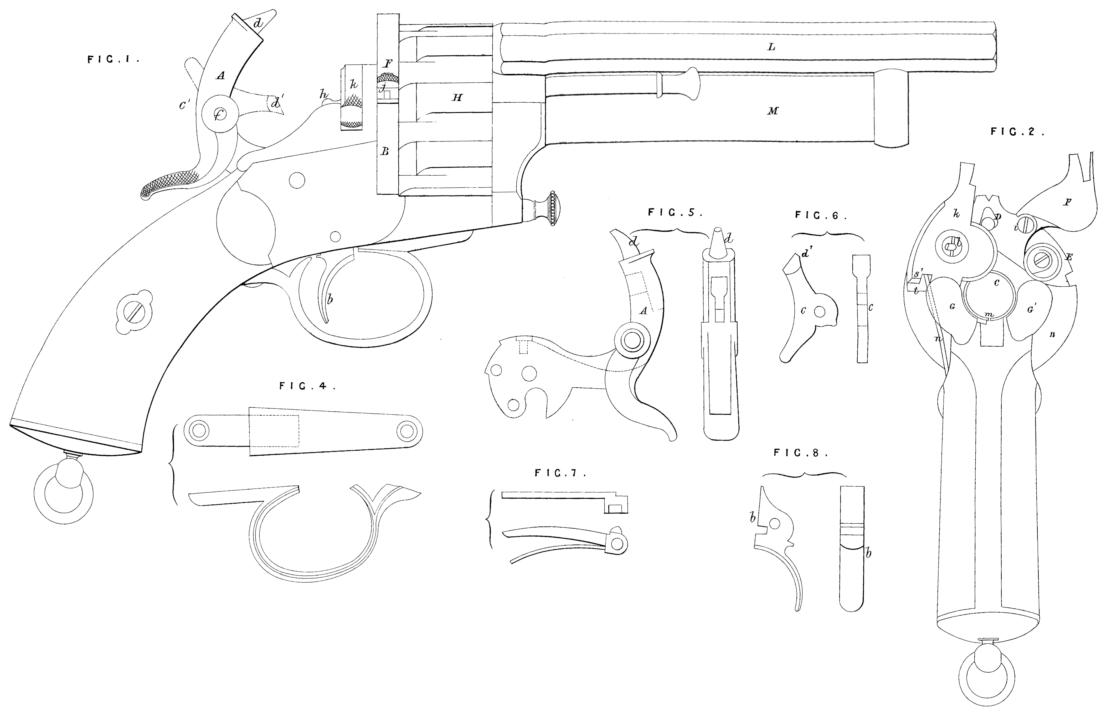
The accompanying Drawings represent a revolver constructed according to my Invention.
Figure 1 is an elevation of the right-hand side; Figure 2 is an end view taken in front of the hammer, which is here removed to show the breeches and the charge chamber; Fig. 3 is an elevation of the left hand side, the barrels being in section.
The revolver is composed of four main parts ; first , the lock, comprising the trigger, the hammer, and parts connected therewith; secondly, the breech which receives the parts specially intended to facilitate the loading; thirdly, the revolving chambers; and, fourthly, the barrels. The lock and parts connected therewith are not different to those commonly employed, except that the hammer A is constructed in a special manner; it is composed of two jointed pieces; one, which is the main body is actuated directly by the trigger b; the other, c, is terminated by a striking pin d, and can turn on the axis f. This turning movement allows the shooter to give the part c the position shown in black ink. or that c^1 shown in red ink; a strong spring holds it firmly in either case. In the position c the hammer will act by its pin d on the ball cartridge in one of the revolving chambers, and in the other position c^1 it produces the percussion indirectly by striking with its nose d^1 on the pin h of the piece k, which serves as an obturator and cartridge extractor. The breech against which the revolving portion turns is a sort of metal disc B pierced by two cylindrical holes C, D; the first in the centre corresponds with the central barrel, the second at the circumference described by the centre of the chambers of the revolving portion gives passage to the pin d of the hammer when it proceeds to strike the cartridge. At the circumference of the disc B an opening or space E is formed intended exclusively for the intro duction of the ball cartridge for loading the revolving chamber; this space is filled up after loading by a piece F adjusted therein, and which can turn on an axis i; a spring j keeps this piece against the breech. The obturator k also turns on a hinge; it carries a pin 7 which produces the percussion on the central cartridge. This obturator after being lowered is firmly held between the breech B and two strong metal shoulders G, G^1, which form a body with the lock plate. As soon as the obturator k is raised for loading the central barrel the extractor m, which is a movable half cylinder at the entrance of the central barrel, pushes the base of the cartridge and allows of withdrawing it after the discharge.
The action is as follows :— In rising the hook s of the obturator k bears obliquely on the tail t of the lever arm u of the extractor m which moves on a fixed pin v; the half cylinder of the extractor m thus springs from the barrel and throws out the case of the cartridge. A strong spring n keeps the obturator k in its two positions, the one raised, the other in place. The revolving portion H turns round the central barrel on which it is fitted so as to move easily; a small rod O fulfils the functions of an extractor for the barrels of the revolving portion. The two barrels L and M are parallel; that corresponding to the revolving chambers is rifled to receive the ball cartridge; it is longer than the other, which is cylindrical internally to receive the grape or duck shot cartridge, shown in Figs. 26 and 28. The charge of this cartridge is composed of a main conical ball p, on the neck of which the tying of the paper case is effected; of a base or socket 9, which receives the fulminate and powder; and between this base and the ball p a number of lead pieces r, r^1, r^11, is placed, each being equal to a third of the cylindrical section of the cartridge. Fig. 27 shows the cartridge for the upper barrel.
Figs . 4 to 25 are views in detail of the parts of the fire-arm. Figure 4 is the trigger guard; Fig. 5, the main hammer A; Fig. 6, the central hammer c; Fig. 7, the sear or lever with its spring; Fig. 8, the trigger; Fig. 9, the lock plate; Fig. 10, the spring of the central hammer; Fig. 11, the shutter F of the revolving part; Fig. 12, the extractor m; Fig. 13, the revolving part; Fig. 14, the locking screw; Fig. 15, the mainspring; Fig. 16, the spring of the shutter of the central barrel; Fig. 17, the trigger spring; Fig. 18, the spring of the shutter of the revolving part; Fig. 19, the claw of the mainspring; Fig. 20, the rod O and its spring; Fig. 21, the upper barrel L; Fig. 22, the central barrel M; Fig. 23, the central shutter K; Fig. 24, the spring of the stop of the revolving part; Fig. 25, the stop of the revolving part.
SPECIFICATION in pursuance of the conditions of the Letters Patent, filed by the said François Alexandre Le Mat in the Great Seal Patent Office on the 12th April 1869.
TO ALL TO WHOM THESE PRESENTS SHALL COME, FRANCOIS ALEXANDRE LE MAT, of New Orleans, in the State of Louisiana, in the United States of America, Colonel, send greeting.
WHEREAS Her most Excellent Majesty Queen Victoria, by Her Letters Patent, bearing date the Thirteenth day of October, in the year of our Lord One thousand eight hundred and sixty-eight, in the thirty-second year of Her reign, did, for Herself, Her heirs and successors, give and grant unto me, the said Francois Alexandre Le Mat, Her special licence that I, the said Francois Alexandre Le Mat, my executors, administrators, and assigns, or such others as I, the said Francois Alexander Le Mat, my executors, administrators, and assigns, should at any time agree with, and no others, from time to time and at all times thereafter during the term therein expressed, should and lawfully might make, use, exercise, and vend, within the United Kingdom of Great Britain and Ireland, the Channel Islands, and Isle of Man, an Invention for “Improvements In The Construction Of Revolving And Repeating Fire-Arms,” upon the condition (amongst others) that I, the said Francois Alexandre Le Mat, my executors or administrators, by an instrument in writing under my, or their, or one of their hands and seals, should particularly describe and ascertain the nature of the said Invention, and in what manner the same was to be performed, and cause the same to be filed in the Great Seal Patent Office within six calendar months next and immediately after the date of the said Letters Patent.
NOW KNOW YE, that I, the said Francois Alexandre Le Mat, do hereby declare the nature of my said Invention, and in what manner the same is to be performed, to be particularly described and ascertained in and by the following statement thereof, reference being had to the Drawings hereunto annexed, that is to say:
My Invention has special reference to those revolving fire-arms in which, in addition to the ordinary barrel and revolving breech chambers for ball cartridges, there is a central charge chamber and a separate barrel intended for firing grape or duck shot.
The Invention consists in the combination of parts as herein-after described. This combination comprises the following:— The charging of the revolving breech chambers as well as the central chamber is made at the breech; the explosion in both cases is effected by a pin; the hammer head is composed of two parts articulated together, one of the parts being called the lateral hammer head which acts upon the ball cartridges in the revolving chamber, and the other part called the central hammer head and which acts upon the grape or duck cartridge of the central barrel; the breech of the central barrel carries the pin, and at the same time favors the automatic action of the tilting or rocking cartridge extractor; all the parts of the arm are very strong owing to the particular arrangement.
The accompanying Drawings represent a revolver constructed according to my Invention.
Figure 1 is an elevation of the right-hand side; Figure 2 is an end view taken in front of the hammer, which is here removed to shew the breeches and the charge chamber; Figure 3 is an elevation of the left hand side, the barrels being in section.
The revolver is composed of four main parts ; first, the lock comprising the trigger, the hammer, and parts connected therewith; secondly, the breech which receives the parts specially intended to facilitate the loading; thirdly, the revolving chambers; and, fourthly, the barrels. The hammer is constructed in a special manner; it is composed of two jointed pieces, namely, the piece A which is the lateral hammer head of the revolver; this piece, which is seen in detail in Figure 4, is actuated directly by the trigger b, and the other piece B, seen separately at Figure 5, constitutes the central hammer head and can turn on the axis f, Figure 1; thus the shooter can at will cause the explosion either of the revolving breech chamber H or of the central barrel M by the relative positions of the lateral hammer head A or the central hammer head B. In the position of the hammer head A shewn in Figure 1 if it is lowered by the trigger b it will act by its point d on the ball cartridge in one of the revolving chambers, and supposing the central hammer head B in the position shewn at Figure 1, if the whole hammer head were lowered by the trigger the nose of the hammer head B will strike against the striking pin h projecting from the piece k, which serves as an obturator and cartridge extractor. The breech against which the revolving portion turns is a sort of metal disc E pierced by two cylindrical holes C, D, seen at Figure 2; the first, C, in the centre corresponds with the central barrel, the second, D, at the circumference described by the centre of the chambers of the revolving portion, gives passage to the pin d of the hammer head A when it proceeds to strike the ball cartridge seen separately at Figure 9. At the circumference of the disc E an opening or space e is formed intended exclusively for the introduction of the ball cartridge for loading the revolver chamber; this space is filled up after loading by a piece g adjusted therein and which can turn on an axis i; a spring j, Figure 6, keeps this piece against the breech. The obturator k, Figure 2, also turns on a hinge; it carries the pin h which produces the percussion on the central cartridge M; this obturator after being lowered is firmly held between the breech E and two strong metal shoulders G, G^1, Figure 2, which form a body with the lock plate. As soon as the obturator k is raised for loading the central barrel the extractor m, seen in detail at Figure 7, which is a movable half cylinder at the entrance of the central barrel pushes the base of the cartridge and allows of withdrawing it after the discharge.
The action is as follows:— In rising, the hook s of the obturator k (Figure 2) bears obliquely on the tail t of the lever arm u of the extractor m which moves on a fixed pin v, the half cylinder of the extractor m thus springs from the barrel and throws out the case of the cartridge. A strong spring n (Figure 2) keeps the obturator k in its two positions, the one raised, the other in place. The revolving portion H turns round the central barrel on which it is fitted so as to move easily; for this purpose a groove a separates the interior surface of the barrel from the piece H (see Figure 3) in such a manner that the piece H only bears upon the central barrel M at each end, and the space thus left serves to receive oil. A small rod O, Figure 8, fulfils the functions of an extractor for the barrels of the revolving portion. The two barrels L and M are parallel and of the same length; the barrel L corresponding to the revolving chambers is rifled to receive the ball cartridge, seen at Figure 9. The central barrel M is cylindrical internally to receive the segmental grape or duck shot cartridge, shown in Figures 10, 11, and 12. The charge of this cartridge is composed of a main conical ball p, on the neck of which the tying of the socket z and of fabric or metal is effected; of a base q which receives the fulminate and powder; and between these two extremities a number of lead pieces r, r^1, r^11, is placed at need, each being equal to a third of the cylindrical section of the cartridge (see Figure 12). The powder is placed between the base and the projectiles. The cartridge is separated into two parts, and in consequence of this the union of the base q is effected by being fitted in with the socket z.
And having now described the nature of my said Invention, and in what manner the same is to be performed, I declare that I claim,—
First. The general combination and arrangement of parts of my improved revolving and repeating fire-arms, substantially as described and represented in the Drawings hereunto annexed.
Secondly. The double-acting jointed hammer head, substantially as described and represented in Figures 1, 2, 3, 4, and 5 of the accompanying Drawings.
Thirdly. The charging of the arm at the breech by means of the piece g working on an axis, substantially as described and represented in Figures 1 and 2 of the accompanying Drawings.
And, fourthly. In combination with the revolver chamber H, I claim the groove x (Figures 1 and 3) formed therein for the purpose of containing oil or other lubricator to diminish friction.
In witness whereof, I, the said Francois Alexandre Le Mat, have hereunto set my hand and seal, this Twentieth day of March, in the year of our Lord One thousand eight hundred and sixty nine.
F. A. Le MAT. (L.S.)
Witness ,
Ch. Armengaud,
Civil Engineer,
Boulevard de Strasbourg, 23,
Paris.