
Britain 2210
A.D. 1865, 28th August. N° 2210.
Breech-loading Revolvers.
LETTERS PATENT to Prosper Polain, of Liege, in the Kingdom of Belgium, Gentleman, for the Invention of “IMPROVEMENTS IN BREECH LOADING REVOLVERS.”
Sealed the 30th January 1866, and dated the 28th August 1865.
PROVISIONAL SPECIFICATION left by the said Prosper Polain at the Office of the Commissioners of Patents, with his Petition, on the 28th August 1865.
I, PROSPER POLAIN, of Liege, in the Kingdom of Belgium, Gentleman, do hereby declare the nature of the said Invention for “Improvements In Breech Loading Revolvers,” to be as follows:—
The fire-arm which forms the subject of the present Invention consists of a cylinder provided with a number of chambers, in which are enclosed a corresponding number of short chambers or barrels to receive separate charges or cartridges. Each of these barrels or charge chambers is composed of a short tube or barrel, and they are all screwed at their outward ends into openings or holes in a circular plate or disc which is common to them all. This circular plate or disc, with the short tubes or barrels thereon, is capable of being slidden forward or backward on a central pin or axis which passes through the disc and also through the centre of the enveloping cylinder. Openings are made in the sides of this cylinder for the purpose of introducing the cartridges or charges into the charge chambers, to do which the latter must be moved forward so that the charges may be inserted at their rear ends. When all the barrels are charged they are drawn back, and the edges of their open ends enter circular grooves made in the end plate of the enveloping cylinder, and thus the breeches are rendered close.
This Invention is also applicable to revolvers constructed on the break-down system. In such arms it is by drawing back the cylinder which opens the charge chambers, whereas in other systems the cylinder remains stationary and the charge chambers are opened by moving forward the barrels.
SPECIFICATION in pursuance of the conditions of the Letters Patent, filed by the said Prosper Polain in the Great Seal Patent Office on the 28th February 1866.
TO ALL TO WHOM THESE PRESENTS SHALL COME, I, Prosper Polain, of Liege, in the Kingdom of Belgium, Gentleman, send greeting.
WHEREAS Her most Excellent Majesty Queen Victoria, by Her Letters Patent, bearing date the Twenty-eighth day of August, in the year of our Lord One thousand eight hundred and sixty-five, in the twenty-ninth year of Her reign, did, for Herself, Her heirs and successors, give and grant unto me, the said Prosper Polain, Her special licence that I, the said Prosper Polain, my executors, administrators, and assigns, or such others as I, the said Prosper Polain, my executors, administrators, and assigns, should at any time agree with, and no others, from time to time and at all times thereafter during the term therein expressed, should and lawfully might make, use, exercise, and vend, within the United Kingdom of Great Britain and Ireland, the Channel Islands, and Isle of Man, an Invention for “Improvements In Breech Loading Revolvers,” upon the condition (amongst others) that I, the said Prosper Polain, my executors or administrators, by an instrument in writing under my, or their, or one of their hands and seals, should particularly describe and ascertain the nature of the said Invention, and in what manner the same was to be performed, and cause the same to be filed in the Great Seal Patent Office within six calendar months next and immediately after the date of the said Letters Patent.
NOW KNOW YE, that I, the said Prosper Polain, do hereby declare the nature of my said Invention, and in what manner the same is to be per formed, to be particularly described and ascertained in and by the following statement, reference being had to the Drawing hereunto annexed, and to the letters and figures marked thereon (that is to say):—
The fire-arm which forms the subject of the present Invention consists of a cylinder provided with a number of chambers, in which are enclosed a corresponding number of short chambers or barrels to receive separate charges or cartridges. Each of these barrels or charge chambers is composed of a short tube or barrel, and they are all screwed at their outward ends into openings or holes in a circular plate or disc which is common to them all. This circular plate or disc, with the short tubes or barrels thereon, is capable of being slidden forward or backward on a central pin or axis, which passes through the disc and also through the centre of the enveloping cylinder. Openings are made in the sides of this cylinder for the purpose of introducing the cartridges or charges into the charge chambers, to do which the latter must be moved forward, so that the charges may be inserted at their rear ends. When all the barrels are charged they are drawn back, and the edges of their open ends enter circular grooves made in the end plate of the enveloping cylinder, and thus the breeches are rendered close.
This Invention is also applicable to revolvers constructed on the break down system. In such arms it is by drawing back the cylinder which opens the charge chambers, whereas in other systems the cylinder remains stationary, and the charge chambers are opened by moving forward the barrels.
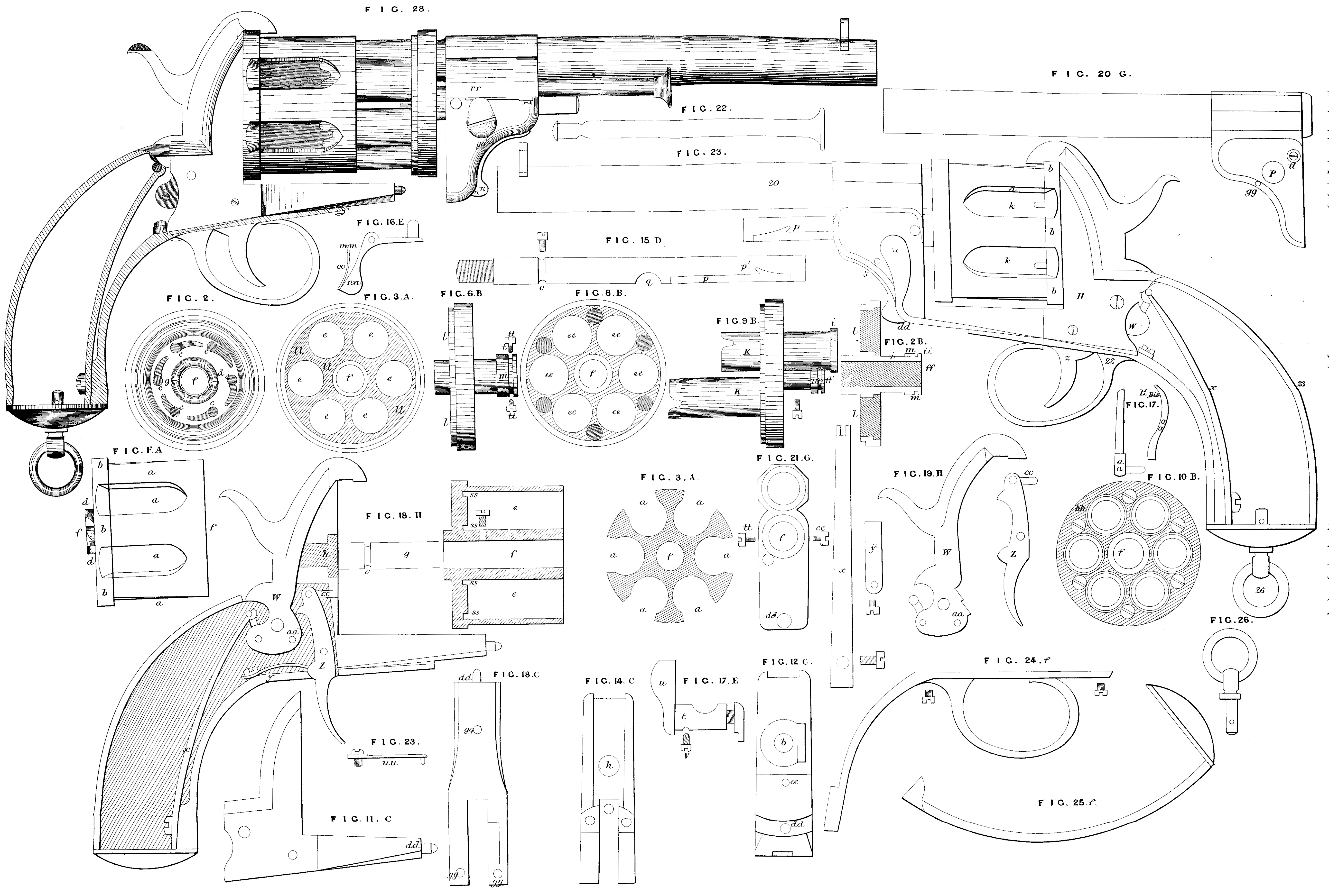
In the accompanying Drawing A (Fig. 1) represents the cylinder, which is made all in one piece, and is provided with several chambers, and also with a breech b of about a quarter of an inch in thickness. At the centre of the breech is formed a wheel d, having six teeth. This wheel projects a little beyond the breech. The chambers have openings a on the periphery of the cylinder for the purpose of introducing the charges. The cylinder A has an opening f through its centre (see the sectional view, Fig. 4) for the reception of the central spindle g (Fig. 18 H), fixed to the breech h. At the rear end of the cylinder are annular recesses s, s, into which fit the small barrels here after described. At the breech or rear end of the cylinder (see Fig. 2), are the stop notches c with their guide groove. Fig. 3 represents the division of the chambers, and also the part I cut away to receive the part l of the disc Fig. 6; Fig. 4 is a longitudinal section of the cylinder; Fig. 5 is a cross section of the cylinder taken through the middle where the openings a are situate. The disc and its tube B, Fig. 6 are made in one piece, the disc is provided with openings e, e, (Fig. 8), corresponding with the chambers in the cylinder, and in which are inserted the small barrels k, with their flanges i, (Fig. 9), which flanges fit into recesses i, Fig. 7. The small barrels are held in place by means of screws h, h, Fig. 10; the heads of the screws being sunk in countersunk holes in the discs so as not to project therefrom. The lower part of the disc has a projecting part 2, about the tenth of an inch in thickness, to afford a deeper hold to the screws of the small barrels. The projecting part l fits into a corresponding recess l in the cylinder Fig. 3, or the small barrels might be attached by means of solder. Fig. 9 shews two of these small barrels, one being attached to the disc, and the other detached therefrom. A groove m is formed round the disc tube. This part of the tube fits into a hollow made above the rear end of the large barrel at n, Fig. 21. Two small screws t, t, Fig. 21, are fitted into the groove at the flat sides of the rear end of the large barrel. This arrangement allows the disc to turn upon the central spindle, and serves as a guide to the small barrels in order to open or close the pistol, and to hold the disc and large barrel together. The small barrels are caused to enter the grooves s, s, at the bottom of the cylinder chambers, and thus prevent any escape of gas. Fig. 7 is a section of the disc and its tube. The central spindle D (Fig. 15) is screwed to the body of the breech plate c (Fig. 11) at the part h (Fig. 12). A small groove o (Fig. 15) is made at its base, where is adjusted a screw passing through the cylinder A (Fig. 4) for the purpose of keeping this latter in place at the same time that it allows of its turning. In the upper part of the spindle is aa groove p, and at the top of this groove is a recess p^1, which serves as a stop to the slide guide. In the middle of the spindle is a nick q to receive the closing key.
Fig. 16 represents the slide guide which serves to guide and maintain the barrel in its horizontal position. It is composed of a spring catch m, m, which slides in the groove p of the spindle, and on reaching the recess p^1 it enters or springs into it, and holds the pistol open. The catch m, m, is worked by means of a trigger n, n, behind which is a spring o, o, which acts upon and keeps the catch in the recess p of the groove p. On pressing upon the trigger n the catch will be freed from the notch, and the pistol may be readily brought to the closed position. The trigger piece n and its accessories are fixed in the breech of the barrel by means of a screw 9, 9, which serves as the fulcrum, as seen in Fig. 28. The key F (Fig. 17) passes through the flat part of the breech of the large barrel; it is composed in the interior of an excentric t, which is operated by means of an exterior lever u. On this latter being raised the disc and its small barrels (held together as above stated with the large barrel) will slide upon the central spindle; when on the contrary the movement of the lever is reversed the pistol will be closed, and all the parts firmly held in their positions. The extent of motion of the lever is limited by a small screw v situate below the barrel breech (see Fig. 12).
The lock (Fig. 18) is single acting, and is composed of a hammer W (Fig. 19), a large spring x, a guide for the cylinder and its spring a, a, a trigger z with its catch or pin c, c, and a small trigger spring y. The catch pin c, c, is screwed to the upper part of the trigger z opposite to a perforation C, C, (Fig. 12) in the breech plate, and opposite to the stop notches c in the cylinder, Fig. 2. Each time the hammer is raised the catch pin will enter this perforation into the groove, and coming in contact with the notch in the cylinder will stop it, and remain in that position until pressure is removed from the trigger; Fig. 11 is a side view of the breech plate; Fig. 12 is a front view of the same. In the middle thereof at h is the aperture for the central spindle D, and a portion cut away for the reception of the cylinder guide a, a, Fig. 19^bis, and also the six- toothed wheel d on the breech cylinder. Below is the perforation c, c, for the passage of the catch pin; d^1 is a pin by which this plate is attached to the main barrel; Fig. 13 as an underneath view of the breech plate, at its upper part is the connecting pin d^1 above mentioned; and 9, 9, are holes for screwing on the trigger guard; Fig. 14 is a back view of the same; Fig. 20 is a side view of the main barrel; Fig. 21 is an end view of the same. In the middle is the orifice f for the reception of the central spindle outside, which is a part n cut away for the reception of the part m of the disc tube. The two screws t, t, represented in this Figure pass through the flat part of the rear end of the barrel, and into the groove of the disc tube; v is a hole for the reception of a screw which serves to limit the motion of the lever (Fig. 17); d^2 is an orifice for the reception of the connecting pin d on the breech plate.
Fig. 22 represents a rod for discharging the cartridge cases from the cylinder; it is placed in an enlargement r’, r, on the rear of the barrel (see Fig. 28). A small spring U, U, (Fig. 23) is set underneath this enlargement, which spring is provided with a catch for taking into the nick x, x, of the rod, and holding it steady. In order to hold the rod more securely the head of the connecting screw of the closing key (Fig. 17) is made of an oval form, so that when the key is closed the oval part of this screw head bears against the spring U, U, and secures the rod; Fig. 24 represents the trigger guard; Fig. 25 the butt or handle, and Fig. 26 the suspending ring; Fig. 27 shews a complete pistol closed, and Fig. 28 shews the same open.
Having now described my Invention of “Improvements in Breech-loading Revolvers,” and having explained the manner of carrying the same into effect, I claim as the Invention secured to me by Letters Patent as aforesaid, the cylinder provided with side openings for the introduction of the charge in combination with a series of short tubes or barrels attached to a disc or plate, and mounted on a central shaft on which the working parts revolve as herein set forth.
In witness whereof, I, the said Prosper Polain, have hereunto set my hand and seal, the Eighteenth day of February, in the year of our Lord One thousand eight hundred and sixty-six.
PROSPER POLAIN. (L.S.)