
US 361819
UNITED STATES PATENT OFFICE.
FRANK A. FOSTER, OF NORWICH, CONNECTICUT.
EJECTOR MECHANISM FOR REVOLVERS.
SPECIFICATION forming part of Letters Patent No. 361,819, dated April 26, 1887.
Application filed February 1, 1887. Serial No. 227,335. (No model.)
To all whom it may concern:
Be it known that, FRANK. A. FOSTER, a citizen of the United States, residing in the city Norwich, county of New London, and State of Connecticut, have invented a certain new and useful Improvement in Revolving Fire-Arms, which improvement is fully set forth and described in the following specification, reference being had to the accompanying sheet of drawings, in which–
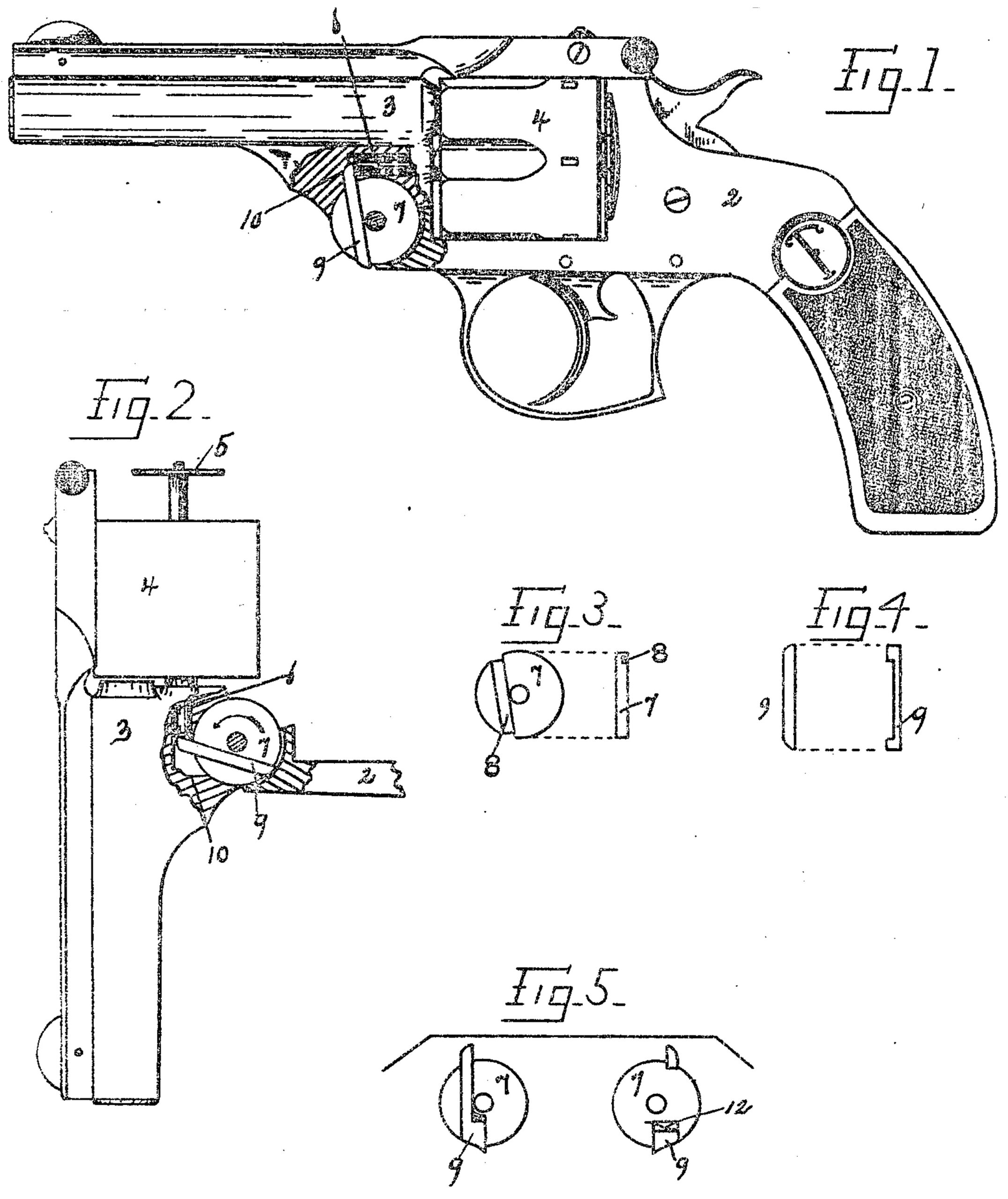
Figure l is a side view, partly in longitudinal section, of a revolver having my improvement attached thereto. Fig. 2 is a similar view of the barrel and frame-strap, but showing the barrel swung wide open and the extractor and its connections returning to their respective seats in the barrel or cylinder. Fig. 3 shows detached views (face and edge) of the lifter-disk 7, and Fig. 4 shows corresponding views of the slide 9. In Fig. 5 I have illustrated a modification of my invention, which is fully explained hereinafter.
Heretofore “hinge’ or breakdown revolvers (to which class my invention relates) have been provided with so called “lifters,” located within the hinge-leaves, having a radial or tangential arm adapted to engage the extractor-stem to check the extractor as the barrel and cylinder are swung outward away from the recoil-shield, and thus discharge the empty cartridge cases. There have been added to such lifter-disks latches or catches of various descriptions, which cause said radial arm to act against the force of the retractor-spring until released by engagement with the barrel as said barrel continues to move on its hinge. So far as I am acquainted with the state of the art, the radial arm, with a single exception, has been an integral part of the lifter-disk, forming, when ready for use, a device of such irregular outline that it has been expensive to produce. My immediate object is to simplify the construction of such lifters and latches, and thereby reduce in a considerable degree the cost of the complete arm. With this object in view have produced a lifter-disk which may be circular in outline, dispensing with the integral radial heretofore used and substituting a sliding attachment which may serve both as lifter-arm and latch, all of which I will proceed to describe in detail.
Referring now to the annexed drawings, the reference-figure 2 indicates the frame of a revolver, 3 the barrel, and 4 the cylinder, Within which lies the extractor 5. The stem 6 of said of extractor extends through the cylinder and enters the barrel, as shown in the drawings.
Located centrally within the hinge-leaves is my lifter-disk 7, formed as a circular washer, of the same diameter as the hinge-leaves, and having a transverse channel, 8. (See Fig. 3.) This channel 8 is forward of the central pivot-hole when the arm is assembled, and is cut preferably to a depth about one-half the thickness of the disk. Within the channel 8, I place a piece, 9, fitted to slide easily endwise, having its lower end projecting slightly below the disk to engage the frame, but beveled on its front side, as shown, to “cam’ against the barrel as the barrel swings on its hinge, as will be understood by referring to the drawings.
The upper concealed end of the movable piece 9 projects upward beyond the disk 7 to a point where it may engage the end of the extractor-stem and perform the office of the integral arms, above described.
The body or central portion of the slide 9 should be of a thickness sufficient to just fill the channel 8; but I prefer to make the projecting ends of the same thickness as said disk, thus adding strength to the wearing-surfaces. and at the same time providing angular shoulders which limit the endwise movement of said slide in either direction.
It will now be understood by those familiar with this class of devices that when the barrel is swung forward on its hinge the upper end of side 9 will check and hold the extractor stem until its lower end is released from engagement with the frame, when the usual retractor-spring within the cylinder will throw said stem forward, this last action being substantially identical with that of lifters as heretofore commonly constructed. It will now become necessary to slide piece 9 downward to its normal position ready for engagement with the frame again. This I may accomplish without the use of springs or other movable elements by beveling the upper end of slide 9 and arm shaping the engaging-wall of the chamber in the barrel, as at 10, so that as the barrel approaches its closed position it engages said slide and moves it downward.
In the modification shown in Fig. 5 I have increased the width of piece 9 at one end and have inserted in the disk a spring, 12, which acts to return said piece to its normal position when the barrel is closed after discharging the empty shells.
When formed as herein described, the disks 7 may be made from a solid steel bar in an ordinary screw-machine, or may be punched, flattened, and turned off in “gangs” on a suitable mandrel.
My lifting device as a whole is extremely simple and strong, may be cheaply produced, is positive in its action, and is practically indestructible.
Having thus described my invention, I claim–
In a revolver of this class, in combination with the extractor-sten and retractor-spring, a lifter-disk in the hinge parts, having located therein a transversely-movable piece, one of whose ends is extended beyond the perimeter of said disk to engage said extractor-stem, the opposite end being similarly extended to engage the frame, substantially as described, and for the objects set forth.
FRANK. A. FOSTER.
Witnesses:
FRANK H. ALLEN,
TYLER. J. HOWARD.