
US 339300
UNITED STATES PATENT OFFICE.
IVER JOHNSON, OF WORCESTER, MASSACHUSETTS.
REVOLVER.
SPECIFICATION forming part of Letters Patent No. 339,300, dated April 6, 1886.
Application filed October 12, 1885, Serial No. 179,661. (No model.)
To all whom it may concern:
Be it known that I, IVER JOHNSON, of city and county of Worcester and commonwealth of Massachusetts, have invented certain new and useful improvements in Fire-Arms; and I do hereby declare the following to be a full, clear, and exact description of the same, reference being had to the accompanying drawings and letters of reference marked thereon, forming a part of this specification, and in which–
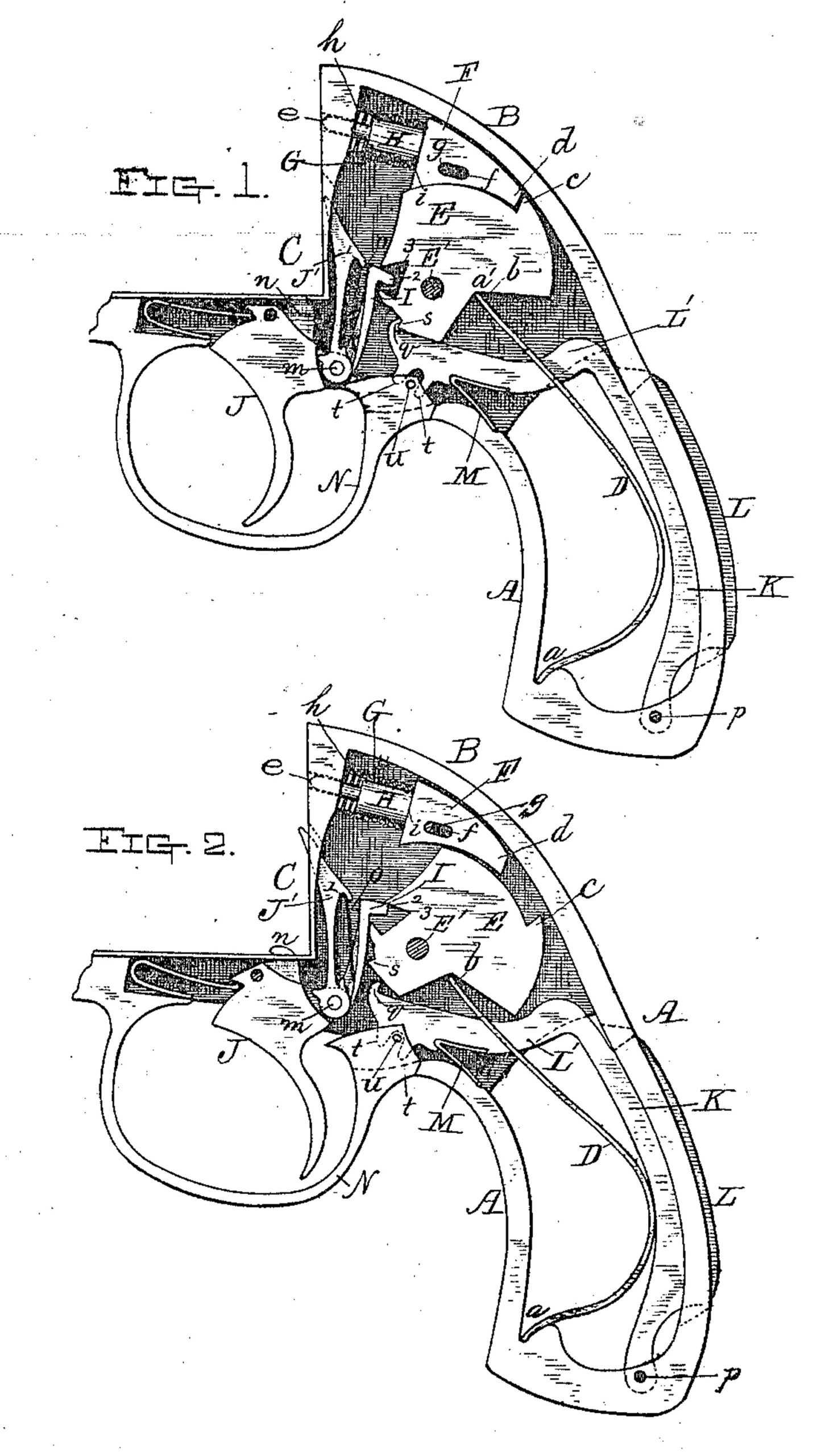
Figure 1 represents a side view of so much of the rear part of the fire-arm with the side plate removed as is necessary to illustrate my present improvements; and Fig. 2 represents a similar view with the parts in position as they appear when the trigger is drawn back to fire the arm, as will hereinafter more fully described.
To enable those skilled in the art to which my invention belongs to make and use the same, I will proceed to describe it more in detail.
D is the mainspring, one end, a, being fitted in a notch in the rear portion of the handle, while the other end, b, bears against the rear part of the hammer E in the angle a’, the hammer E being pivoted at E’ to the frame or receiver B, pin E’ being shown in section. Hammer E is provided with a projection, c, which, when the hammer is allowed to fly forward, strikes against the end d of the sliding firing-pin F and drives its point e through the seat C and fires the cartridge. Firing-pin F is provided with a slot, f, through which a pin, g, (shown in section,) passes, said pin being support in the side of frame or receiver part B, and when the arm is at rest a spiral spring, G, fitted on the rounded part H, forces firing-pin F back against pin g, as fully indicated in Figs. 1 and 2 of the drawings, spring G pressing against the inner surface or face, h, of the seat C and shoulder i of the firing-pin F. The rounded part H, which supports the spring G, prevents the point e from being driven too far beyond the outer face of seat C, and as soon as the momentum of hammer E has been expended upon firing-pin F and the cartridge exploded or fired spring G, which had been compressed by the action of the hammer, forces the firing-pin back into its normal position, as shown in the drawings. The front upper edge of hammer E forward of hammer projection c is made in curved or circular form to fit the curved under side of the rear slotted part of the firing-pin F, which rests and slides thereon, as fully indicated in the drawings. By this arrangement the firing-pin is not liable to be clogged, while the friction thereof upon the lower surface of the firing-hole is very slight; consequently the operations of the hammer and firing-pin in practice are very easy, certain, and effective. Hammer E is raised by a sear or raiser, I, pivoted at m to the trigger J. Lever J’, for rotating the cylinder, is also pivoted to the trigger at m. Trigger J is also provided with a cylinder-stop, n, which is raised in position for holding the cylinder when the trigger is drawn back, as is indicated in Fig. 2 of the drawings. The rounder part of a U-spring, o, is fitted into a recess or concavity, 1, in the upper part of lever J’, while its lower ends bear out against the lower parts of lever J’ and sear or raiser I, thereby keeping said lever J’ and sear I in proper positions, the former to turn the cylinder and the latter to force back the hammer E when trigger J is drawn back.
Point 2 of sear I fits in a notch, 3, in hammer E, as fully indicated in the drawings, and its action upon the hammer will be readily understood upon referring to the relative position of the parts shown in Fig. 2, in which case the point 2 is about to slip from the notch in the hammer and allow the latter to fly forward against the firing-pin F.
To the rear inside of handle A a safety-lever K, is pivoted at p, and which lever is also provided with a projection, L, extending through a slot in the handle, as indicated in the drawings, while the upper or forward part, L’, of said lever is curved down and passes under hammer E with a lug or catch, q, upon its upper side, to catch upon the projection s of hammer E whenever the latter is returned to its normal position, as shown in Fig. 1, and when in this position the hammer cannot be drawn back by the action of the trigger, or other wise, until after the lever K has been forced down to release said hammer, as shown in Fig. 2. The upper part, L’, of lever K passes through, in this instance, a slot in the mainspring D, and is also provided with two fingers, t, which straddle a guide-pin, u, fingers t working in a slot in the guard N. A two-armed spring, M, is fitted between the under side of the part L of lever K and the inside of the handle-frame A, to press the free end of said lever up against the hammer E, to insure the locking thereof whenever mainspring D throws it into the position shown in Fig. 1.
From the foregoing description it will be seen that projection L must first be depressed to unlock hammer E before trigger J can be drawn back to operate the hammer, and, further, that hammer E cannot be accidentally forced against the firing-pin, since the trigger, sear, and hammer are locked together by the action of lever K. It will be observed that the bow part only of safety-lever K extends beyond the handle, and this only in the scalloped part thereof; consequently the handle can be firmly grasped and held without liability of unlocking the hammer, while, when desired, by a slight depression of the center portion of the hand the bow part of safety-lever K can be depressed in the scallop of the handle and the hammer unlocked. Accidental or premature firing of the arm is therefore well guarded against.
In using the arm the hollow of the hand first presses in projection L and unlocks hammer E, when the contraction of the finger draws back trigger J and fires the arm. Lever K, being of a single piece, locks the hammer far more effectually and securely than is the case when several parts or levers are employed for that purpose, in connection with a movable part arranged in the handle to be pressed into unlock the hammer preparatory to firing. Then, again, my arrangement of a lever, extending under the hammer and locking the same from its lower forward edge, causes the parts to work and wear more uniformly and securely than would be the case if the arrangement of parts was such as to bring the strain upon the hammer upon its upper part or above its pivot, where nearly all the other strain in operating the hammer comes.
It will be understood that lever K may be arranged somewhat differently, and also constructed in a somewhat different form, and yet accomplish substantially the same results and practical advantages above set forth.
Having described my improvements in fire-arms, what I claim, and desire to secure by Letters Patent, is–
1. In revolving fire-arms, the combination, with bow safety-lever K L’, provided with projection L, extending through a slot in the scalloped part of the handle, within which said lever is hinged, of slotted guard N, guide pin u, and fingers t on the end L’ of lever K, said fingers straddling pin u and working in said slot in guard N, all substantially as and for the purposes set forth.
2. In revolving fire-arms, the combination, with chamber or receiver B and handle A, of mainspring D, provided with a slot for the passage of the end L’ of lever K, and hammer E, provided with a projection, s, to engage with the lug or catch g on the inner end of lever K L’, substantially as and for the purposes set forth.
3. In revolving fire-arms, the combination, with hammer E, provided with a circular forwardly-projecting part for the rear curved part of the firing-pin to rest and slide upon, and an upward projection, c, for striking the firing-pin, of firing-pin F, fitted to rest upon the forward curved part of the hammer, and provided with slot f, to receive pin g to limit its motion, and spring G, for retracting the firing-pin, all substantially as described.
IVER JOHNSON.
Witnesses:
HENRY L. MILLER,
THOS. H. DODGE.