
US 46562
UNITED STATES PATENT OFFICE.
PATRICK HAUGHIAN, OF NEW YORK, N.Y.
IMPROVEMENT IN REVOLVING FIRE-ARMS.
Specification forming part of Letters Patent No. 46,562, dated February 28, 1865.
To all whom it may concern:
Be it known that I, Patrick Haughian, of the city, county, and State of New York, have invented a new and useful Improvement in Revolving Fire-Arms; and I do hereby declare that the following is a full, clear, and exact description of the same, reference being had to the accompanying drawings, forming part of this specification, in which—
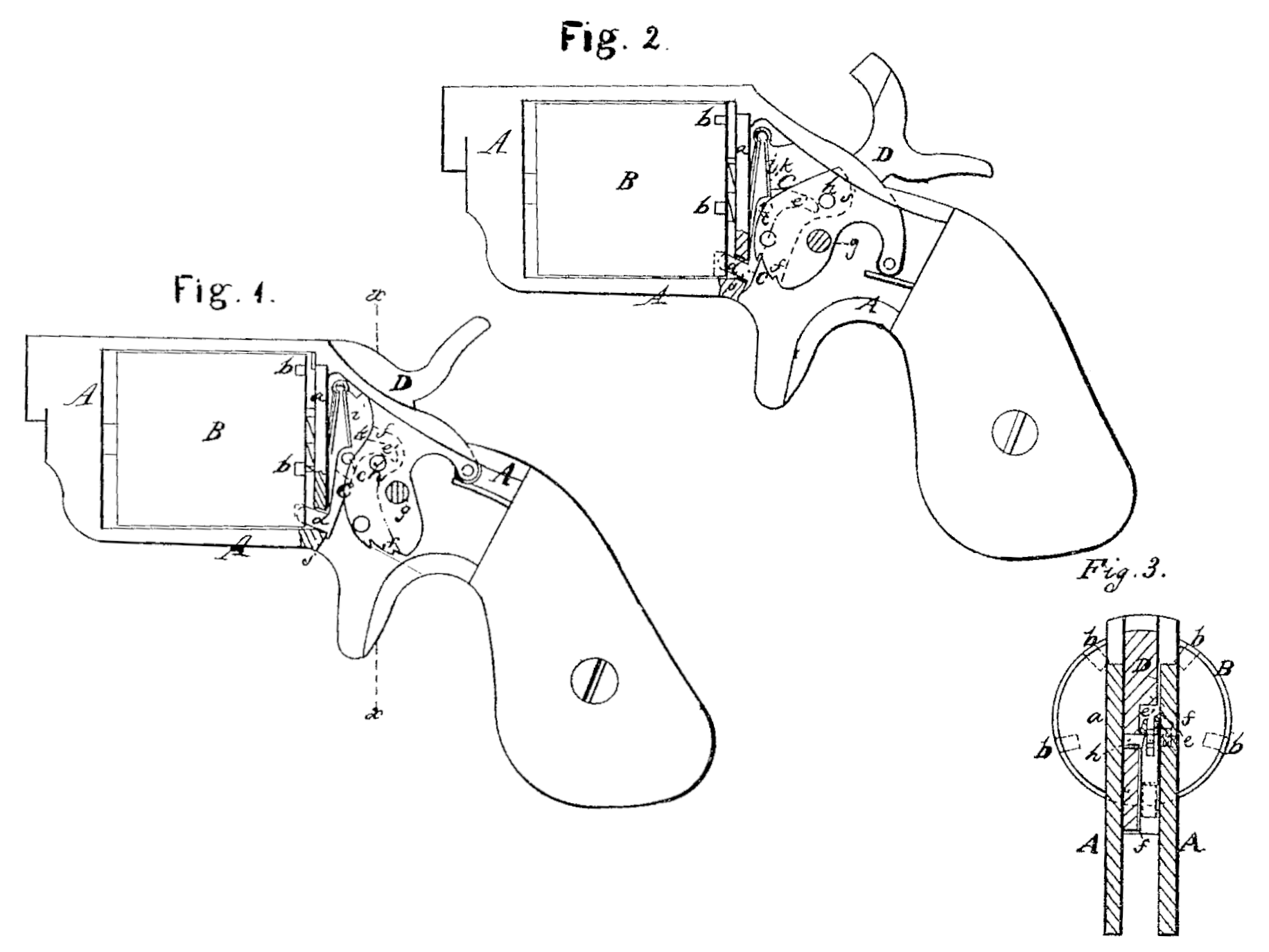
Figures 1 and 2 are side views of a pistol with my improvement, showing the cap-plate of the lock removed to expose the working parts, and representing the parts in different positions. Fig. 3 is a transverse vertical section of the same in the plane indicated by the line x x in Fig. 1.
Similar letters of reference indicate corresponding parts in the several figures.
This invention consists in the arrangement of the cylinder stop-lever or catch to work in rear of the cylinder, behind the recoil-shield, and between it and the hammer; also, in a peculiar form of the said stop or catch and arrangement of its spring, whereby the said stop or catch is permitted to be arranged in rear of the recoil-shield without interfering with other parts of the lock.
To enable others skilled in the art to make and use my invention, I will proceed to describe the Construction and operation of one mode in which I have successfully applied it to practice.
A c is the frame of the arm, of substantially the same form as in many of the revolving fire arms heretofore constructed.
B is the cylinder, having the stop-notches b b in its rear end instead of in its periphery, as is most commonly the case.
C is the stop-lever or catch, working in planes parallel with the axis of the cylinder on a fulcrum-pin, c, which attaches it to the right side of the frame A, between the recoil-shield at and the hammer D. This lever or catch is formed with an elbow, and the fulcrum-pin is at the elbow. One arm thereof is nearly vertical, having a downward direction from the fulcrum, and it has the stop-tooth d at its lower end. This arm is made perfectly stiff. The other arm, which is turned back from the fulcrum, is slotted vertically, so as to make it present two prongs, e e’, one of which, e, is situated close to the interior of the right-hand side of the frame, as shown in Fig. 1, and the other, e, is flexible laterally, but rigid vertically. The hammer has a cavity, f f, in the front part of its right side, as shown in Fig. 3, and in dotted outline in Figs 1 and 2, to make room for the operation of the stop or catch, and is furnished above the ping, on which it Works, with a pin, h, for operating on the under surface of the spring side e’ of the upper arm of the stop or catch to lift the said arm as the hammer is being drawn back, and thereby cause the lower arm to recede from the cylinder and withdraw the tooth d from the notch b which it has occupied; but the prong e’ is of such length that before the hammer arrives at full-cock the pin h passes its extremity and leaves the lever or catch under the influence of the spring i, which acts to produce the forward movement of the lower arm and bring the stop-tooth against the cylinder, so that it will enter the next notch b. The tooth d works through a hole, i, in the recoil-shield. The end of the pin h is beveled, as shown in Fig. 3, toward its lower side, and the prong e’ of the upper arm of the stop-lever is beveled in a corresponding manner, so that as the hammer falls, it will simply press the prong et aside without moving the lever on its fulcrum.
This mode of operating the stop-lever or catch is substantially the same as is used in many other revolving fire-arms in which the dog is arranged below the cylinder, and it is only in the arrangement of the stop lever or catch and in its combinations with the parts hereinafter mentioned that my improvement consists. The spring i is of V form and applied above the fulcrum of the stop-lever or catch between the recoil-shield and a shoulder, k, on said lever.
By the arrangement of the stop-lever or catch C behind the cylinder and between the recoil-shield and hammer the several parts of the lock are brought into a very compact form, and the frame, not having to be slotted or cut away above or below the cylinder for the reception of the said lever or catch, can be made much thinner and lighter, which gives the arm a better appearance and makes it more handy to carry.
What I claim as my invention, and desire to secure by Letters Patent, is—
1. The arrangement of the cylinder stop lever C, to work in rear of the cylinder upon a fulcrum-pin, c, situated behind the recoil-shield and between it and the hammer, substantially as herein specified.
2. The construction of the so-arranged lever of the elbow form herein described, and represented in Figs. 1 and 2, in combination, with the within-described arrangement of the spring i, to operate upon a shoulder, k, above the fulcrum of the said lever, substantially as herein set forth.
3. A spring-sided stop-lever or catch arranged to work in rear of the cylinder and between the recoil-shield and the hammer, in combination with a cam on the hammer, in the manner and under a mode of operation substantially as described.
P. HAUGHIAN.
Witnesses:
Thos. J. Douglas,
J. W. Coombs.