
British 1346
LETTERS PATENT to Frederick Collier Balcewell, of No. 6, Haverstock Terrace, Hampstead, in the County of Middlesex, for tlie Invention of “ Improvements in Rotating Breech Fire-arms.”—A communication from Josiah Ells, of the United States of North America.
Sealed the 7th December 1855, and dated the 13th June 1855.
PROVISIONAL SPECIFICATION left by tlie said Frederick Collier Bake well at tbe Office of the Commissioners of Patents, with his Petition, on the 13th June 1855.
I, Frederick Collier Bakewell, of No. 6, Haverstoek Terrace, Hampstead, in the County of Middlesex, do hereby declare the nature of the said Invention for “ Improvements in Rotating Breech Fire-arms,” being a communication from Josiah Ells, of the United States of North America, to be as follows :—
The Invention consists, in the first place, in the application to the rotating chambered breech (and forming part thereof) of a short tubular extension terminating in a collar, which collar fits into a corresponding recess in the bracket of the barrel, the object being to serve the twofold purpose of preventing the spindle on which the breech rotates from fouling, and of connecting & locking the breech, the latter object being further secured, if required, by a screw at the end of the spindle inserted into a female screw in the bracket.
Another part of the Invention consists in the application of a moveable stud that fits into a hole in the shoulder of the trigger, in combination with a hammer having a bevelled edge and a notch at the extremity of its toe, by means of which stud on pulling the trigger the hammer is raised to full cock, and may be either allowed to stand so by slightly catching into the notch, or the fire-arm may be fired at once by drawing the trigger a little farther. The moveable stud, which is retained in its projecting position by a spring (yielding laterally by the pressure of the bevelled edge of the hammer), allows the descent of the hammer, and then recovers its former position for repeating the action.
Another part of the Invention consists in the application of a double spring (or of a spring lever & spring), so as to allow sufficient play in the trigger, and thereby giving it the requisite reacting force without using so strong * spring as would be otherwise necessary, the cam & friction roller that ad against the springs being so arranged as to equalize the resistance in drawing back the trigger throughout its whole course.
Another part of the Invention consists in a mode of locking the rotating breech at the moment of firing, by means of a bolt in combination with a cam shoulder on the trigger, and a hexagonal or polygonal neck on the rotating breech, the latter being nevertheless permitted to be freely rotated by hand or otherwise when the trigger is not drawn back, thus allowing the breech to be turned round for loading without touching the trigger.
Lastly, the Invention further consists in the application of a self-acting safety bolt, attached to the guard plate of the fire-arm in such manner thd it may be readily slipped in front of the trigger when the fire-arm is loaded, so as to cause the trigger slightly to withdraw the hammer from the percussion cap on the nipple, and thus prevent accidental discharge by a blow on the hammer, the safety bolt receding automatically when the trigger is drawn back for firing.
SPECIFICATION in pursuance of the conditions of the Letters Patent, filed by the said Frederick Collier Bakewell in the Great Seal Patent Office on the 11th December 1855.
TO ALL TO WHOM THESE PRESENTS SHALL COME, I, Frederick Collier Bakewell, of No. 6, Haverstock Terrace, Hampstead, in the County of Middlesex, send greeting.
WHEREAS Her most Excellent Majesty Queen Victoria, by Her Letters Patent, bearing date the Thirteenth day of June, in the year of our Lord One thousand eight hundred and fifty-five, in the eighteenth year of Her reign, did, for Herself, Her heirs and successors, give and grant unto me, the said Frederick Collier Bakewell, Her special licence that I, the said Frederick Collier Bakewell, my executors, administrators, and assigns, or such others as I, the said Frederick Collier Bakewell, my executors, administrators, and assigns, should at any time agree with, and no others, from time to time and at all times thereafter during the term therein expressed, should and lawfully might make, use, exercise, and vend, within the United Kingdom of Great Britain and Ireland, the Channel Islands, and Isle of Man, an Invention for “Improvements in Rotating Breech Fire-arms,” being a communication from Josiah Ells, of the United States of North America, upon the condition (amongst others) that I, the said Frederick Collier Bakewell, by an instrument in writing under my hand and seal, should particularly describe and ascertain the nature of the said Invention, and in what manner the same was to be performed, and cause the same to be filed in the Great Seal Patent Office within six calendar months next and immediately after the date of the said Letters Patent.
NOW KNOW YE, that I, the said Frederick Collier Bakewell, do hereby declare the nature of the said Invention, and in what manner the same is to be performed, to be particularly described and ascertained in and by the following statement:—
The Invention consists, in the first place, in the addition to the fore part of the rotating chambered breech (and forming a part thereof) of a short tubular extension terminating in a collar, which collar fits into a corresponding recess in the bracket of the barrel. This improvement is intended to serve the twofold purpose of preventing the spindle on which the breech rotates from fouling, and of connecting and locking the breech, the latter object being further secured, if required, by a screw at the end of the spindle inserted into a female screw in the bracket.
Another part of the Invention consists in the application of a moveable stud that fits into a hole in the shoulder of the trigger, in combination with a hammer, having a bevelled edge and a notch at the extremity of its toe, by means of which stud on pulling the trigger the hammer is raised to full cock, and may be either allowed to stand so by catching slightly into the notch, or the fire-arm may be discharged at once. The moveable stud, which is retained in its projecting position by a spring, by yielding laterally by pressure on the bevelled edge of the hammer allows the descent of the latter, and then recovers its former position for repeating the action.
A third part of the Invention consists in the application of a double spring or a spring lever and spring, so as to allow sufficient play in the trigger, and thereby giving it the requisite reacting force without using so strong a spring as would otherwise be necessary, the cam that acts against the spring being so arranged as to equalize the resistance of the trigger to the finger throughout its sweep.
A fourth part of the Invention consists in a mode of locking the rotating breech at the moment of firing, by means of a locking bolt in combination with the cam shoulder on the trigger, and a hexagonal or polygonal neck on the rotating breech, the latter being, nevertheless, permitted to be freely rotated by hand or otherwise when the trigger is not drawn back, thus allowing the breech to be turned round for loading without touching the trigger.
Lastly, the Invention further consists of the application of a self-acting safety bolt, attached to the guard plate of the fire-arm in such manner that it may be readily slipped in front of the trigger when the fire-arm is loaded, so as to cause the trigger slightly to withdraw the hammer from the percussion cap on the nipple of the breech, and thus to prevent accidental discharge by a blow on the hammer, the safety bolt receding automatically when the trigger is drawn back in firing.
Having thus stated generally the several parts of the Invention, I will proceed to describe in detail the construction, arrangement, and operation of the improved fire-arm, referring particularly to the accompanying Drawing, comprising twelve Figures, which forms part of this Specification, and in each of which Figures like letters are employed to indicate corresponding parts. I must also observe, that though the description and Drawing refer only to rotating breech pistols, commonly called “ revolvers,” the Invention is equally applicable to guns, rifles, and fire-arms generally, by the necessary changes of size and arrangement, which any skilful mechanic can readily make. In the following description I shall be obliged to refer to several parts of fire-arms commonly known and used, without, however, claiming originality in any other parts than those noticed in the foregoing statement of the parts claimed as new.
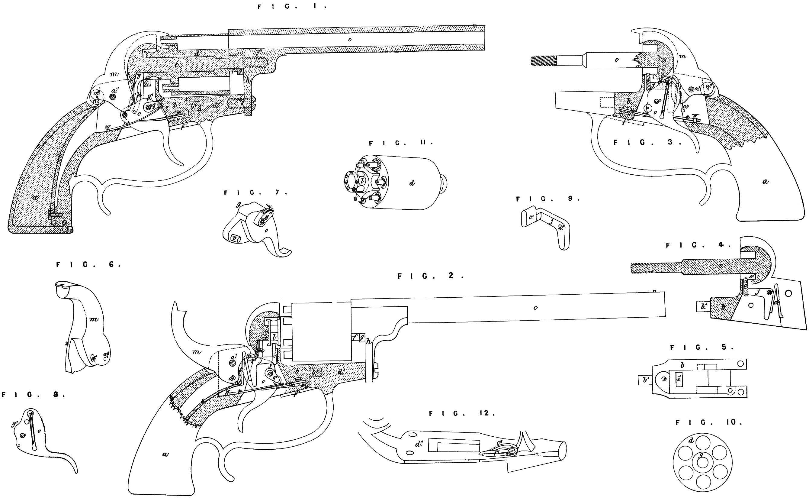
In the Drawing accompanying this Specification, Figure 1 is a sectional side view of a revolving pistol constructed with the improvements, excepting that the locking bolt is removed to exhibit the other parts more clearly; Figure 2 is a side view of a similar pistol, exhibiting the several parts of the lock in their positions when the trigger is drawn back, and the pistol is cocked ready for firing; Figure 3 is a sectional view of the stock and lock frame of a pistol, showing the reverse side of the interior of the lock, the several parts being in their positions when the trigger is fully drawn back immediately after firing and before the trigger is released; Figure 4 is a sectional view of the lock frame with all the parts removed excepting the locking bolt and its spring; Figure 5 is a view of the under side of the lock frame, all the works of the lock being removed.
In Figure 1 the parts of the lock are represented in a state of rest in their positions before the trigger is pulled ; in Figure 2 the hammer is raised by the action of the moveable stud on the cam-shaped toe of the hammer, and is at full cock, the side of the stud resting in the notch in the toe, and preventing the fall of the hammer until the trigger is pulled farther back; and the cam shoulder of the trigger, pressing the level face of the locking bolt against the squared surface of the neck of the rotating chamber, locks it in its proper position; the slightest touch on the trigger would now fire the pistol. In Figure 3 the hammer has fallen, and the trigger, if released, would instantly regain its position for repeating the fire.
Figure 6 is a perspective view of the hammer, designed to show more clearly the chamfered edge, against which the moveable stud in the trigger works; Figure 7 is a perspective view of the trigger, exhibiting the position of the moveable stud and of the shoulder on which the trigger spring rests; Figure 8 is a side view of the trigger, showing the side not seen in Figure 7; Figure 9 is a perspective view of the locking bolt; Figure 10 is a view of the front end of the rotating breech; Figure 11 is a perspective view of the rotating breech; Figure 12 is a perspective view of the trigger guard frame, showing the position of the safety bolt.
In the several Figures referred to, a is the stock of the pistol; h is the lock plate; c is the barrel; d is the rotating breech. From the lock plate b9 and in a suitable position, extends the spindle being attached to the rotating breech by the tubular extension/, and sustained by the spindle as already described, is fastened to the guard frame d1 by a screw $ or spring bolt, which may readily be removed, and when so removed the barrel may be unscrewed from the spindle, and the rotating breech is then free to slip off it. The shape and construction of the rotating breech d is seen in Figure 11. At the extremity of the neck of the breech are ratchets t, i, equal in number to the number of chambers in the breech. These ratchets or projecting points need not project far, being only intended to catch against the point of the finger fc, which serves, as herein-after described, to rotate the breech. Near the extremity of the neck of the rotating breech, the circumference, which is elsewhere circular, is of the shape shown at l (Figures 2 and 11), with flattened sides, the number of sides being the same as the number of chambers in the breech, that portion of the breech thus forming a sort of polygonal cylinder, so that a section of it at right angles to the axis in a pistol with six chambers would present a regular hexagon, one flattened side being opposite each chamber in the breech.
The several pieces of the lock are shown (with the exception of the locking bolt) jn Figure 1 ; the locking bolty with its spring being shown in Figure 4.
The reverse side of the several parts is shown in Figure 3, wherein m is the hammer, which turns on the hammer pin a1. At S is the main spring, attached to the lock frame, and passing up through the hollow stock of the pistol. The extremity of the main spring rests on a friction roller it at the heel of the hammer, which forces it down when released from the trigger. The under side of the hammer is broad and curved, and comes to a point or nearly so at the toe. The front edge of the hammer is chamfered or bevelled, and, from being broad at the base, gradually narrows to an edge at the top of the recess in the side of the hammer (see Figures 3 and 6), made to allow of the passage of the trigger o. The trigger is of the shape shown in Figures 7 and 8 ; it works in the lock on the trigger pin a2. Near the point the trigger is reduced to nearly half its thickness by a recess made to allow7 of the passage of the toe of the hammer m. In this recess and near the point of the trigger is the moveable studjp, which is a short steel rod or stud, with a rounded projecting point, and flat head, inserted in a cylindrical bore in the trigger. It is kept in its place by a fine spring r inserted in a groove in the trigger (shown in Figures 3 and 8), the head of the stud preventing its being forced out of the trigger by the spring. This stud is fitted nicely into its hole, so that while it moves back and forward when pressed in the direction of its length, it remains firm when the projecting side of the stud presses against the toe of the hammer. The shoulder q in the side of the trigger serves as the bearing point of the spring lever t, which transmits to the trigger the force of the spring w, the spring lever resting on a friction roller v in the shoulder. The spring lever t and spring u form a double spring, which is very useful when a strong spring is required and a good deal of play is necessary, being more efficient and less liable to get out of order. The arrangement is as follows:—The spring lever t is placed with its point resting on the friction roller in the shoulder q of the trigger, and the other extremity, which has a circular hole through it, is slipped over a pin w (see Figure 3) in the base of the lock plate. This spring lever is not screwed or otherwise fastened down, but is kept in place by the point of the strong spring u, the base of which is fastened to the under side of the lock plate (see Figure 2) by a screw s\ which screws into a hole at x.
In Figure 1 the relative positions of the hammer and trigger before firing, and the position of the moveable studjp, are clearly shown. The base of the hammer near its toe rests on the side of the moveable stud. The relative positions of the centre pins a} and a2 are so adjusted, that when the trigger is drawn back, the stud p, pressing on the broad base of the toe of the hammer, raises it up, the hammer as it rises pressing down the main spring S. As the hammer rises, the turning point a1 being stationary, the point a3, (being the centre of the friction wheel at the heel of the hammer,) which sustains the whole pressure of the main spring S, gradually descends, until the trigger is drawn back so far as to raise the hammer to the point of full cock (as shown in Figure 2), when the centre a1 is almost immediately under the centre a\ thus gradually reducing the effective resistance of the main spring, so that the power required to raise the hammer gradually diminishes as the hammer rises instead of increasing, as in the locks of fire-arms ordinarily, till at the point of full cock a veiy slight touch is enough to fire the pistol, the main spring S gaining strength or leverage as the hammer falls, and exerting its greatest force when the hammer strikes the percussion cap. When the moveable stud p has raised the hammer, and the latter is drawn as far back as represented in Figure 2, it slips into a notch near the toe of the hammer (seen in Figure 1 immediately in front of the moveable stud) with a slight click, causing a sensation perceptible by the person using the pistol, and will thus stand at full cock although the notch is very slight, because the pressure of the spring on the toe of the hammer at that point is very small. If the trigger is now drawn a little farther back (to the position shewn in Figure 3), the stud p will pass out of the notch and over the extremity of the toe of the hammer, which is immediately liberated, and fires the pistol. So soon as the pressure of the finger is removed from the trigger after firing, the trigger recedes, and the moveable stud sliding up the chamfered edge of the hammer until it comes into the position shown in Figure 3, (where the stud comes to the point of the hammer marked 2 in Figure 6,) the point of the stud slips over the thin edge of the hammer and down over its side, the spring r allowing the stud to recede as the thickness of the hammer increases until it reaches the base of the hammer,’ when the stud slips off its edge, and the trigger resumes its place, as shown in Figure 1, with the edge of the stud lying under the toe of the hammer ready for repeated action.
When the pistol has been fired, and the trigger and other parts have returned to their first positions, it is necessary before firing again that the rotating breech be turned so far round as to bring the next loaded chamber in a line w ith the barrel. This is accomplished during the pulling of the trigger for the second fire by means of the finger ky which is connected with the trigger by a pin projecting from its side at the lower extremity, which enters into a corresponding hole in the side of the trigger between the moveable stud and tho centre pin er. The finger k lies in a recess y in the side of the lock plate (see Figure 1.) This recess opens into the circular recess round the base of the spindle e, in which the neck of the rotating breech is inserted. The spring cl at the back of the finger k presses against the wall of the recess, and presses the finger forward. When the trigger is not drawn back, as in Figure 1, the finger k does not come in contact with the ratchets i9 i, but as the trigger is drawn back it raises the finger until it enters the recess in which the ratchets i, i, are situated, and, pressing against one of them, turns the rotating breech just far enough to bring another loaded chamber exactly in line with the barrel, in which position it is retained, as herein-after explained, until the pistol is fired. By the falling of the trigger after firing, the finger k is withdrawn, and resumes its first position.
The locking bolty, the shape of which is more clearly shown in Figure 9, is designed to lock the rotating breech in its proper position at the moment of firing, leaving it at all other times to bp freely rotated by the finger &, or by the hand, at pleasure. In Figure 4 this locking bolt is shown in place in a recess in the side of the lock plate made for its reception. The spring c2, which fits into a notch in the wall of the recess, presses against the leg of the locking bolt, and presses the head o1 of the bolt through an opening el (see Figure 4) into the recess round the spindle e (see Figures 2 and 4). Now, the neck of the rotating chambered breech having as many sides as there are chambers in the breech, whenever the breech is turned round, the flat head of the bolty, pressing by means of the spring c2 on the hexagonal neck l, causes the breech always to rest in such a position that one of the chambers is in an exact line with the barrel, the spring c2 being strong enough to prevent the breech from turning round accidentally, and yet permitting it to be rotated freely when required. When the trigger is drawn back to the point of full cock, or nearly so, as in Figure 2, a hump or cam shoulder gl comes in contact with the under side of the head o1 of the locking bolt (as in Figure 2), and presses the face of the head of the bolt firmly against one of the fiat sides of the neck of the rotating breech, thus preventing its rotation during firing, and until the trigger is released. This arrangement enables a person in loading the breech to rotate it freely without touching the trigger; whereas in revolving fire-arms as usually constructed, the trigger has to be pulled part way back, and to be held in that position before the breech can be turned.
When the pistol is loaded, the end of the hammer ordinarily presses against the percussion cap placed on the nipple of the chamber, which is then on a line with the barrel. Under these circumstances, an accidental blow on the hammer might explode the cap and fire the pistol, as frequently occurs. To remove this danger, and at the same time to place no obstacle to an immediate use of the pistol, there is attached to the lock plate b, immediately in front of the trigger, a small bolt or pin f\ which turns on a pin or centre i. The point of this safety bolt fits into a small hole in the trigger, when the latter is drawn back just far enough to withdraw the face of the hammer from contact with the percussion cap. As the trigger spring u presses the trigger forward, the safety bolt cannot get out of place until the trigger is drawn back still farther, and when this is done, as in firing the pistol, a slight spring c3 throws the safety bolt out of the way automatically, (see Figure 12.)
Having thus given a detailed description of the several parts of the Invention, I wish it to be understood that I disclaim originality in the use of rotating chambered breeches, excepting so far as relates to the mode of attaching and rotating them. I also disclaim originality in the use of recoil shields as such, the strain occasioned by any attempt at recoil of the breech being sustained, and any actual recoil being prevented by the tubular extension in the fore part of the chambered breech, and its locking connection with the bracket of the barrel. The parts claimed as new are specifically stated at the commencement of this Specification. The advantages of the improved fire-arm are, its simplicity of construction, which renders it less liable to miss fire or get out of order; the great ease and rapidity with which it may be fired ; and its standing cocked by merely pulling the trigger.
In witness whereof, I, the said Frederick Collier Bake well, have hereunto set my hand and seal, this Eleventh day of December, in the year of our Lord One thousand eight hundred and fifty-five.
FREDK COLLIER BAKEWELL. (t.s.)