
US 12555
UNITED STATES PATENT OFFICE.
FREDERICK NEWBURY, OF ALBANY, NEW YORK.
IMPROVEMENT IN FIRE-ARMS.
Specification forming part of Letters Patent No. 12,555, dated March 20, 1855.
To all whom it may concern:
Be it known that I, Frederick Newbury, of the city of Albany, State of New York, have invented certain useful Improvements in the Construction of Fire-Arms, of which the following specification, with the drawings hereto attached as part of the same, gives a full and complete description.
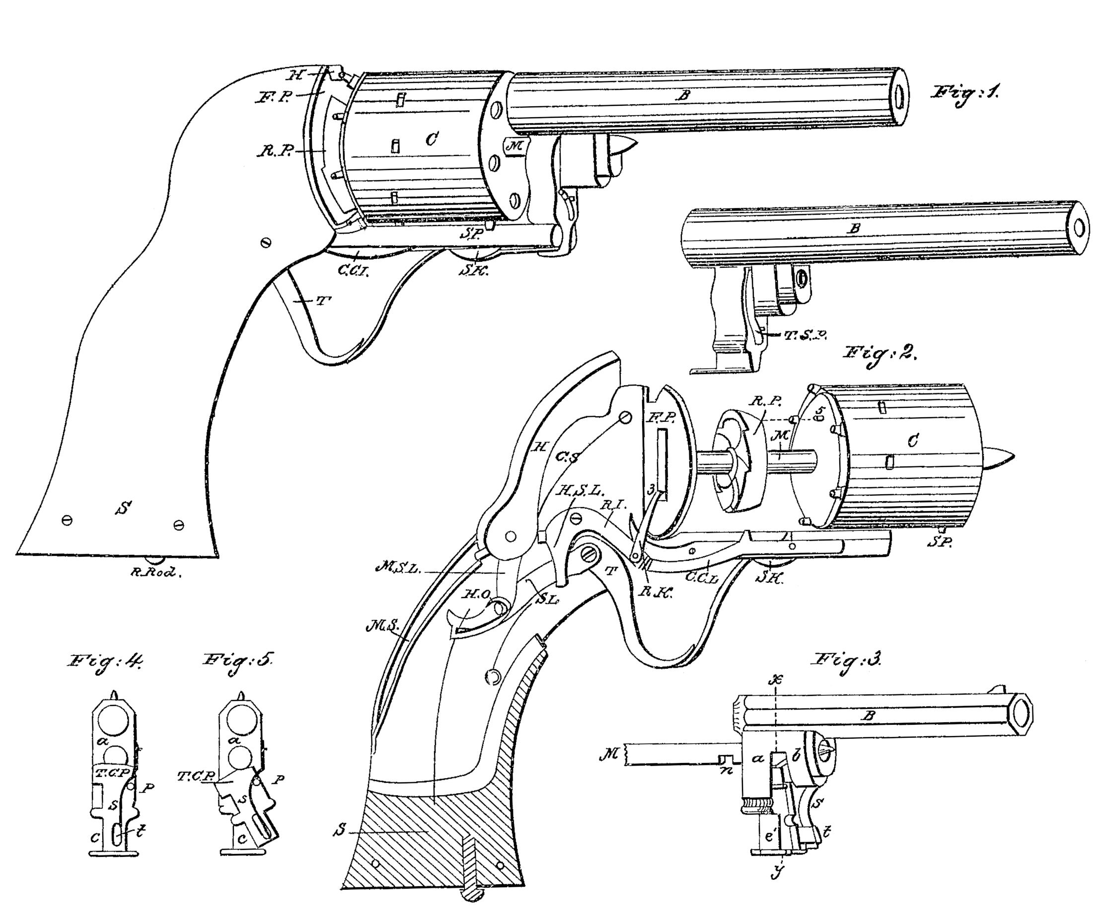
No.1 represents a perspective view of a pistol arranged after my plan; No. 2, another perspective view of the same with the parts partially detached and a portion of the outer covering of the stock removed to show the operating machinery of the lock.
Similar letters in both numbers representing the same parts of the apparatus.
In its practical operation my pistol resembles Colt’s pistol in having one barrel with a many-chambered cylinder for loading, each chamber being brought successively in line with the barrel. It also resembles Allen’s pistol in having a many-chambered cylinder capable of being revolved and discharged by the action of the trigger; but differing from both of these fire-arms in important respects forming the matter of my invention.
S is the stock of the pistol, terminated at its front extremity by the face-plate F P, being a metallic disk fitted thereon, from the center of which and at right angles thereto proceeds the mandrel M, which is the axis on which the cylinder C, containing the charges, revolves in the usual method of many-chambered cylinders. The cylinder itself is constructed as in Colt’s pistol, with the priming-nipples projecting from the rear of each chamber. Between the cylinder and the face-plate a metal disk, R P, is placed, of less diameter than the cylinder, having on its back face, near its periphery, ratchet-indentations cut, hence called the “ratchet-plate.” These indentations are placed equidistant, and are equal in number to the chambers in the cylinder, their intent being to cause the cylinder to revolve by means of the apparatus hereinafter described, so as to bring the chambers to range successively with the barrel. On its front face and near the periphery, but not shown in the drawings, is a slot or sunk cavity, part of an arc, to receive a pin, 5, which projects from the rear of the cylinder, the slot being just long enough to permit the cylinder to revolve so far as to bring two chambers in succession in line with the barrel, Through the face-plate a vertical slot is made opposite the ratchet-indentations in the ratch-plate, to permit the passage of a lever, R K, Whose upper end is bent and fashioned into a pawl, 3, intended to operate in the ratchet-teeth to throw the ratchet-plate around from the right to the left hand.
The lever R K is pivoted to a lever, R L, called the “ratchet-lever,” which extends backward, and is pivoted near its upper end, from which point it curves backward and downward in a sort of hook form, H S L. On the under part of the lever the cam end of the trigger T operates so as to throw it up, and with it the lever R K, with its ratchet, and thus move the ratchet-plate. The under edge of the hook H S L rests against a pin at the pivoting of the trigger and sear-lever, by which the ratchet-lever is pressed back to its first position as the trigger itself falls back after firing. To the back end of the trigger is attached the sear lever S L, which also projects backward with its rear end slightly curved upward. The upper edge of the sear-lever presses upward against a pin, 4, being kept in position by a spring placed below it. The sear-lever near its center, by a pin or projection from it, catches into the tumbler MSL, the upper part of which is (in the drawings) concealed within the hinge of the hammer. A notch on the rear of the tumbler (shown in the drawings as a square projection from the rear of the hammer) lies above and against the mainspring MS, which operates the hammer, so that the drawing of the trigger, pressing the tumbler down, relieves the hammer from the pressure of the spring which holds it down against the cylinder. The rear end of the hammer overlies the spring which presses against it, as well as against the tumbler, and the hammer moves round freely and independently of the tumbler on a common axis, and would lie immovable against the cylinder but for the cocking-spring C S—a small spring of just sufficient power to keep the hammer pressed against the mainspring M S.
The hammer has also projecting from its lower edge, over against the upper back edge of H S L, a projection which, when the hammer is slightly raised, catches against a similar projection from the rear of ESL, the operation of which is thus: The hammer, being relieved from the pressure of the mainspring, rises until the two projections described touch each other. This brings the upper edge of the hammer in range with the barrel-sight, where it remains, while the trigger is still moving, until the further pressure of the trigger carries the projection on EIS L past the other one, when, being so released, the hammer is by the action of C S thrown back against the main-spring and rises to the full-cock until the sear-lever S L, as it moves forward, is by the operation of its curved rear end upon the pin 4 thrown out of its catch upon the arm M S L of the tumbler. This being released, the main-spring drives the hammer down upon the priming, firing the piece, at the same time carrying the tumbler back to its first position. As soon as the discharge takes place the pressure of the spring shown underneath the sear-lever throws that lever backward, carrying with it the ratchet-lever by the pin at the pivoting of the sear and ratchet levers referred to in the description of the sear-lever, which projects so as to catch the crooked arm H S L, the other end of the ratchet-lever drawing down the pawl R K.
It will be noted that the drawing of the trigger had thrown up the end of the lever and pawl and caused the cylinder to revolve a space equal to the distance of one chamber from the next one, so as to bring successively two chambers in range with the barrel. On a repeated pulling of a trigger the same action as just described will be repeated.
My hammer has no projections from it, but when ready for firing, before the trigger is drawn, lies in a cavity in the upper part of the stock, its upper edge being flush with or a line below the surface of the stock. This prevents entirely the casualty of a discharge of the pistol by the accidental catching of the hammer and unexpected snapping of it, or the effects of a violent blow upon the same by a fail or otherwise, both which causes have frequently discharged percussion-arms and produced fatal results. From this position of the hammer when down and the line of direction in which it presses against the nipple results another important advantage. The blow of the hammer forces the cylinder slightly forward and brings the mouth of a chamber against the barrel and holds it firmly there during the explosion, so that none of the elastic gas from the powder can escape and thus weaken the effect of the action upon the ball.
In order to keep the cylinder in its true position with each successive chamber accurately in range with the barrel at firing, there are two stop-levers side by side underneath the cylinder and extending back and within reach of the ratchet-lever. The first one is shown be hind the other in the drawings, with a small part projecting downward, (marked S K,) and has just above this projection, on its upper edge, a stop-catch which, when the loaded cylinder is first put on, is pressed up into a cavity cut for the purpose in the cylinder, the proper position for the cylinder being indicated by a stop-pin (marked SP) near the extremity of the cylinder, which pin must rest against the right-hand side of the stock. When in this position the pin 5 will lie on the left-hand corner of the slot referred to in the description of the ratchet-plate R P.
On drawing the trigger for the first fire the ratchet-lever causes the ratchet-plate to revolve by the action of the fall (in the present case of six-chambered cylinder) one-sixth of its revolution; but as the pin 5 is acting in a slot for that distance, the movement of the plate R P does not carry with it the cylinder, whose first chamber remains in line with the barrel as placed. At the moment of discharge the end of the ratchet-lever touches the stop-catch lever and throws the catch out of its notch, leaving the cylinder free to turn till every chamber has been fired and the stop-pin strikes the left band side of the stock.
The second lever, to keep the cylinder in position after the ratchet has brought it into position, is marked C C L (Cylinder click-lever.) Like the stop-catch lever, it has a projecting catch which enters into cavities on the surface of the cylinder, so that at the moment of firing the ratchet-pawl holds it firmly in one direction and the click-lever catch in the other. This lever is held up to its place by a thin spring placed over its inner arm, and is discharged from its hold by the pressure of the front end of the ratchet-lever.just as the ratchet-pawl begins to act upon the ratchet-plate.
It will be seen that after the discharge of the first chamber the pin 5 connects the movements of the cylinder and ratchet-plate, and they operate together till all the chambers have been fired. When that has been done then the cylinder is to be removed from the mandrel M, reloaded, or replaced by a loaded one. The detaching and attaching the cylinder being a matter of great importance in the successful use of the weapon, I propose the following as a much more secure and handy arrangement than any now used with revolvers.
Figs. 3, 4, and 5 represent this arrangement, 4 and 5 being sections through 3 in a line x y.
ab is the boss, of metal, which projects downward from the barrel B, and is pierced to receive the mandrel M, by which the cylinder and barrel connect with each other and with the stock. It is divided into two limbs by a transverse slot which extends up a little above the center of the mandrel-hole. The limb a has a tenon-shaped extension downward, c, which is fitted to a corresponding mortise in the lower projecting limb of the stock, as shown, Fig. 1. The limb b extends only low enough to form a secure socket for the mandrel. Against the front of the limb a a flat plate, T C P, (thumb-connecting plate,) with a thumbpiece, t, projecting from it, is pivoted at p, Figs. 4 and 5. When this plate coincides with the front of b its upper part passes up through the slot across the mandrel socket-hole, and when the barrel is in its proper position on the mandrel enters the notch in in the lower part of the mandrel, which notch will then coincide with the slot, thus attaching the barrel firmly to the stock. This plate is kept in position by the spring S.
When it is desirable to remove the barrel and replace and reload the cylinder the stock of the pistol is to be taken in the left hand and the barrel grasped with the right, pressing the thumb upon t. This action throws the plate TCP in the position shown in Fig. 5, withdrawing its upper edge from the notch 7, and allowing the barrel to be drawn from the mandrel.
The advantages of the above-described method of constructing revolvers are, as compared with Colt’s revolver, that the action of the trigger allows the piece to cock itself, and makes a thumb-piece unnecessary, allowing the hammer to lie flush within the stock, combining promptness of action with security from accidental discharge; also, that the barrel and cylinder can be removed from and replaced upon the stock with perfect security, and in so much less time that nearly five times the number of shots can be fired in a minute; also, that the disposition of the hammer to press and hold the cylinder against the barrel at the moment of discharge adds much to the effect of the powder on the ball. As compared with Allen’s revolver the use of one barrel lessens its weight, and the arrangement for the independent action of the hammer when firing allows of such a disposition of the discharging-machinery as to require less power to operate the trigger, and consequently less disturbance of aim, as well as to take sight to great advantage.
I claim—
1. The ratchet-plate with its ratchet-indentations and its slot, in combination with the pin by which it connects with the cylinder, also the two stop-levers below the cylinder to regulate and secure the connection between the chambers of the cylinder and the barrel, substantially as set forth in the above specification.
2. The arrangement and combination of the tumbler with the hammer and cocking-spring, to enable the hammer to act independently of the tumbler in the act of firing, also the arrangement of the hammer to lie within the stock and to act in such line of direction upon the nipples as to press and hold the cylinder firmly against the barrel in the act of firing, the whole substantially as set forth in the above specification.
3. The arrangement of the apparatus for disengaging and attaching the barrel with the cylinder to the stock— viz., the thumb-connecting plate or detent with the spring to hold it in place and the notch in the mandrel to receive the detent— substantially as set forth in the within specification.
FREDERICK NEWBURY.
Witnesses:
Richd, Varick DeWitt,
W. C. Miller.