
US 12470
UNITED STATES PATENT OFFICE.
JEHU HOLLINGSWORTH AND RALPH. S. MERSHON, OF ZANESVILLE, OHIO.
IMPROVEMENT IN FIRE-ARMS
Specification forming part of Letters Patent No. 12,470, dated February 27, 1855.
To all whom it may concern:
Be it known that we, Jehu Hollingsworth and Ralph. S. Mershon, of Zanesville, in the county of Muskingum and State of Ohio, have invented certain new and useful Improvements in Repeating Fire-Arms; and we do hereby declare the following to be a full, clear, and exact description of the same, reference being had to the accompanying drawings, making a part thereof, in which—
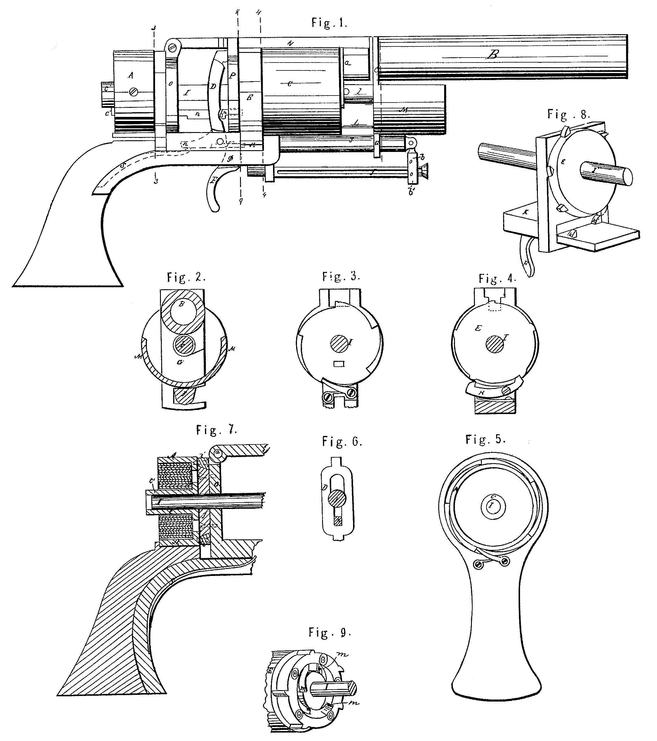
Figure 1 represents a side view of the pistol, but with the cheeks removed to show the interior. Fig. 2 represents a vertical section taken through the line 22 of Fig. 1. Fig. 3 represents an end view at the line 3 3 of Fig. 1, looking to the right. Fig. 4 represents an end view at the line 4 4 of Fig. 1, looking to the left. Fig. 5 represents a rear view of the stock and spring-box. Fig. 6 represents a rear view of the cock or hammer. Fig. 7 represents a central longitudinal and vertical section through the stock, frame, and spring-box. Fig. 8 represents a modified form of escapement, which acts positively and not dependent upon the action of a spring. Fig. 9 represents a perspective view of the plate on the rear of the chambers, taken opposite the line 9 9 of Fig. 1.
Similar letters, where they occur in the several figures, denote like parts.
The nature of our invention relates to the providing of a reservoir of power capable of rotating the cylinder and operating a cock or hammer in concert, so as to produce two or more discharges from a fire-arm without replenishing said power; also, in combining a reservoir of power with a rotating toothed escape-wheel in such manner that at each periodical releasement of said escape-wheel by the operation of a trigger and anchor-escapement the reservoir of power will rotate the chambered breech to the required distance and trip an independent hammer simultaneously; also, in combining a rotating chambered breech with a reservoir of power, so that by the periodical releasement of said reservoir by means of an escape-wheel, trigger, and an anchor escapement said chambers shall be caused to rotate to their required distance and meet the blow of the hammer at the exact instant that each chamber in succession comes opposite the barrel; also, in combining a reservoir of power with an independent cock or hammer, so that by the periodical release of said reservoir of power said hammer shall be tripped at the exact moment that each chamber of the series comes opposite the barrel; also, in so combining the stock with the fire-arm that by turning said stock a spring or springs shall be wound up which shall be capable of actuating the fire-arm for a series of discharges; also, in the peculiar form of guard or protection to the hand on which the fire-arm is supported when taking deliberate aim, so as to guard the hand from accidental discharges of the chambers should they occur; also, in the conical plate and ring by which the stock and spring-box are united to the frame, so as to make a firm connection and at the same time allow the one to be turned on the other for the purpose of coiling up the spring.
To enable others skilled in the art to make and use our invention, we will proceed to describe the same with reference to the drawings.
A represents the reservoir or spring-box for containing the spring, (shown in the section, Fig. 7;) B, the barrel; C, the rotating chamber or breech; D, the hammer; E, the rotating toothed escape-wheel; F, the trigger; G, the latch or catch which holds the chambers and barrel securely to the frame and in their places when the pistol is ready for being discharged. S in dotted lines is the spring for operating or throwing forward the hammer after it has been set or cocked, as will be described.
It will be perceived that there is no projection on the upper part of the pistol to obstruct the aim; that the caps are exploded under such protection as to entirely prevent their flying into the face of the user or impeding in any manner the successful operation of the arm.
. The barrel B is securely fastened to the swinging frame H, which extends rearward and is hinged to the rear division-plate, O, at a, and when in its proper position the latch or catch G, which is united to it by a collar, is brought around in front of the chamber C in such manner that it will clasp the spindle or shaft I, and at the same time the lower part of the stock or frame Y, as seen in Fig.2, and pass between it and the ramrod J, Fig. 1, thus pass between it and the ramrod J, Fig. 1, thus making a permanent fastening, which is readily removed when the fire-arm is to be recharged or the cylinder removed for any purpose.
M is a guard, to be hereinafter described, connected to the latch or catch G, so that when the fire-arm is to be recharged it can be swung with the latch entirely out of the Way of the ramrod. This guard may be detachable, and it is only important when one hand and arm is advanced to support the front of the firearm, as in rifles or slot-guns, or when taking deliberate aim with a pistol.
J is a ramrod slotted and connected to a hinged arm, b, by a pin, b’, passing through said arm and slot, this arrangement admitting of the ramrod being drawn out, reversed, and used for ramming home the charges, and then returned to its place without being at any time detached from the fire-arm.
The rod or spindle I extends rearward into and through the spring-box A, and has upon that portion of it within the spring-box a hook or catch for holding one end of the coiled spring contained therein; or, as we prefer for the more readily facilitating the taking apart of the arm, we pass the end of the spindle I through a sleeve, c’, Fig. 7, and connect the two together by a pin, c”, Fig. 1, so that they shall turn together, and this sleeve c’ serves as an arbor around which the said spring is wound or compressed by the operation of turning the stock, and upon this sleeve the hook or catch for holding one end of the spring may be placed. The spindle in passing forward goes through the rear division-plate, O, and through the hammer D, Fig. 6, and acts or serves as a guide for the movement of said hammer, as seen in said Fig. 6. It passes also through the front division-plate, P, the toothed escape-wheel E, which latter is so connected to as to move with said spindle. This connection may be made by a slot in the escape-wheel and a feather on the spindle in a manner well known to mechanicians. This slot and feather may also serve as a guide for putting together the parts always relatively in the same position. The nipples, which are on the rear of the chamber C, extend through the escape-wheel E, (see Fig. 9,) and said escape-wheel protects them from injury of any kind. At each periodical releasement of the said wheel E and spring or reservoir of power by the operation of the trigger F and the anchor K, said wheel and chambers C are caused to rotate and to present each nipple successively opposite the hammer D, which hammer is, by the periodical release of the power of the coiled spring turning the shaft L, simultaneously tripped by the action of the trigger on the anchor K.
The trigger Fig pivoted at f and acts against a bolt, f’, which passes into the anchor K, so that by the drawing of the trigger backward it will raise up one end of the anchor K, (see Fig. 4) causing that end to catch into or against one of the teeth or projections of the toothed wheel E, and throw out the other end of said anchor, which previously held said wheel, and thus allowing said wheel and chamber connected to it to fly a portion of a revolution and again be caught. When the trigger releases the bolt f’ then the spring i’, under the anchor, again throws up the other end thereof and again catches the wheel, and so on until all the chambers are discharged or the spring or reservoir of power exhausted.
Many modifications for letting out the spring may be essayed, and we have ourselves tried several of them, and among them we would particularly mention the one represented in Fig. 8. This one avoids the necessity of a spring to throw up the anchor, and removes all or any objection that might arise as to the uncertainty of the before-described plan, for as the spring becomes weakened, or if it should break, the chambers might revolve more than their allotted distance. The contrivance represented at Fig. 8 may be called a “dead-beat escapement,” or one working with a positive effect, making it impossible for the cylinder to turn any farther than the given and desired distance. In this figure E may represent the escape-wheel; I, the spindle, and F the trigger, which may be a permanent part of the sliding piece K, having two teeth, k’ k”, so arranged that as one, k’, is slid into the circuit of the escape-wheel the other, k”, will be outside of said circuit, and vice versa. It will thus be seen that it is impossible for the wheel to turn farther than its given distance, as the act of drawing out of the way one of the teeth to allow it to move at all draws the other in the precise spot for catching the first tooth that comes around on the escape-wheel.
Instead of the bolt f’, as represented in Fig. 1, being a separate piece from the trigger, it may be a part of the trigger itself, and release and catch the escape-wheel as it turns by the uncoiling of the spring.
Other forms and methods may be and have been tried; but as they do not change the principle of working an anchor and escapement we do not consider their further notice important.
If considered essential to guard against the breaking of the spring which works the anchor, a ring-trigger may be used and the anchor worked from the trigger regardless of the spring, as the moving of the trigger forward and back by the forefinger in the ring will operate the anchor.
In Fig. 1, L represents a brace which is a part of or connected to the latch G. It rests or bears against the face of the chambers, for the purpose of preventing the friction of said chamber against the end of the barrel at h, and to cause them to turn true on the spindle I. To secure the handle or stock of our fire-arm in such manner as that it may be easily turned to admit of winding up or compressing the spring, and yet not shake or work loosely, we have constructed the bearings or connections in such manner as to allow of the free operation of the turning of the handle, and yet the whole fire-arm remain firm in the hands of the user, viz: i’ i’, Fig. 7, represent in section a conical ring, which is fastened firmly to the box. A by screws or otherwise, and if represent a circular conical plate, fitting exactly said ring i’ i’, said plate being fastened to the rear division-plate, O, by screws which must pass through the closed end of the spring-box, as represented in said Fig. 7, thus making at once a bearing exceedingly simple in its construction and yet very strong, and allowing the handle and spring-box to be turned upon the frame with great readiness.
The click by which the reservoir-spring in its box is held compressed after having been wound up, as before described, by turning the handle, may be arranged, as seen in Fig. 3, with a corresponding bolt or catch, which takes into the several teeth of the ratchet wheel, and thus holds the spring. Other means than the above may be applied, and we have used others, but only present those we find most simple and efficacious.
A bolt such as is used on many other repeating fire-arms may be used on this one, so that the action of the fire-arm may be withheld, or to prevent any accidental discharge by jarring, falling, or other similar mishap, which is incidental to the use of all fire-arms. It may be so arranged as to pass between the escape-wheel and anchor, so as to prevent any forward motion of the anchors. This would be as simple and effective an application of the bolt as any other, as to check or fasten the anchor locks all the Working parts of the fire-arm.
In loading this arm, after the catch G is raised up the chamber C and escape-wheel E are slipped forward on the spindle just far enough to release said escape-wheel from the anchor, and then the two— for they are connected together— are free to be turned around so as to meet the ramrod J, and be charged. While the chambers and escape-wheel are thus ran forward the nipples can be capped, and when returned, the latch or catch put down, and the handle turned to coil the spring, the fire-arm is ready for a series of discharges.
On the rear of the escape-wheel E, as seen in Fig. 9, is a series of cam-planes, m, corresponding to the number of chambers in the revolving breech. Against these planes the end of a bolt, n, Fig. 1, works as follows: When the breech-piece or chamber is released by means of the anchor and trigger, in turning, one of the planes in pushes back the bolt in and brings a shoulder, o, on said bolt against the hammer D, pushing back or cocking said hammer, and in the act of cocking it compresses a spring, s, the point of which presses against the arm p of said hammer, and in this position the arm stands after each discharge, it being caught by the anchor and escapement. Now, by pressing the trigger the anchor is released, the escape-wheel makes another partial rotation, bringing the nipple to the exact spot for receiving the blow of the hammer, and simultaneously letting off the hammer, which carries forward with it the bolt a for the next repeated discharge. It is therefore (after the arm is loaded and the reservoir of power filled) but the simple act of pressing the trigger, which may be a hair-trigger, if desired, that cocks, rotates, and discharges the file arm, so that the aim may be preserved and the whole series of discharges let off without taking down the arm, and that with but a slight touch of the finger.
It may be found in winding up the spring within in the box A, or when, for instance it is only partially wound up, that the stock might not be in exact line with the barrel. To avoid this a ratchet and pawl or “click,” as it is sometimes termed, may be used, which, when the stock or handle is turned in the direction for winding up the spring, will act together and hold, but which, should the handle not be in exact line after the spring is wound up as far as it will go or be required, may be turned back far enough to bring it in line without letting out any part of the spring, as that is caught and held by another click, as heretofore described in Fig. 3.
The guard M is so constructed as to allow an accidental discharge of any of the chambers to escape without striking against any thing or endangering the hand of the user.
Having thus fully described the nature of our invention, we would state that we do not claim a reservoir of power simply for rotating the breech, as that has heretofore been done; but
What we claim therein as new, and desire to secure by Letters Patent, is—
1. The application of a reservoir of power to the rotating of the cylinder or breech, in combination with the cocking and releasing of the hammer in concert, so as to produce two or more discharges from a repeating fire-arm without replenishing said reservoir of power, substantially as described.
2. Combining a reservoir of power with a rotating toothed escape-wheel, anchor, and trigger in such manner that at each periodical releasement of said escape-wheel by the operation of the trigger and anchor or anchor-escapement the reservoir of power will rotate the chambered breech to the required distance and simultaneously trip an independent hammer, substantially as described.
3. So combining a rotating chambered breech with a reservoir of power and cock or hammer as that by the periodical releasement of said reservoir by means of the escape-wheel, trigger, and an anchor-escapement said chambers shall be caused to rotate to their required distance and meet the blow of the hammer at the exact instant that each chamber in succession comes opposite the barrel, substantially as described.
4. Combining a reservoir of power with an independent cock or hammer so that by the periodical releasement of said reservoir of power said hammer shall be tripped at the exact moment that each chamber of the series comes opposite the barrel, substantially as described.
5. So combining the stock with the frame as that by turning said stock a spring or springs shall be wound up which shall be capable of actuating the fire-arm for a series of discharges, substantially as described.
6. The peculiar forum of guard or protection to the hand on which the fire-arm may be supported, so as to guard the hand from any accidental discharge of the chambers when not opposite the barrel, while said accidental discharge may escape from the fire-arm without detriment to the user, substantially as set forth.
7. The conical plate and ring as a means by which the stock and spring-box are united to the frame so as to make a firm connection, and at the same time allow the one to be turned upon the other for the purpose of coiling up or compressing the spring, substantially as described.
JEHU HOLLENGSWORTEH.
RALOH. S. MERSHON.
Witnesses:
L. P. Marsh,
John Haynes.