
US 12235
UNITED STATES PATENT OFFICE.
EDMUND H. GRAHAM OF BIDDEFORD, MAINE.
IMPROVEMENT IN FIRE-ARMS.
Specification forming part of Letters Patent No 12,235, dated January16,1855.
To all whom it may concern:
Beit known that I Edmund H. Graham, of Biddeford in the county of York and State of Maine have invented certain new and useful Improvements in Revolving Fire-Arms; and I do hereby declare that the following description taken in Connection with the accompanying drawings hereinafter referred to, forms a full and exact specification of the same, where in I have set forth the nature and principles o my improvements,by which my invention may be distinguished from others of a similar class together with such parts as I claim and desire to have secured to me by Letters Patent.
The figures of the accompanying plate of drawings represent my improvements.
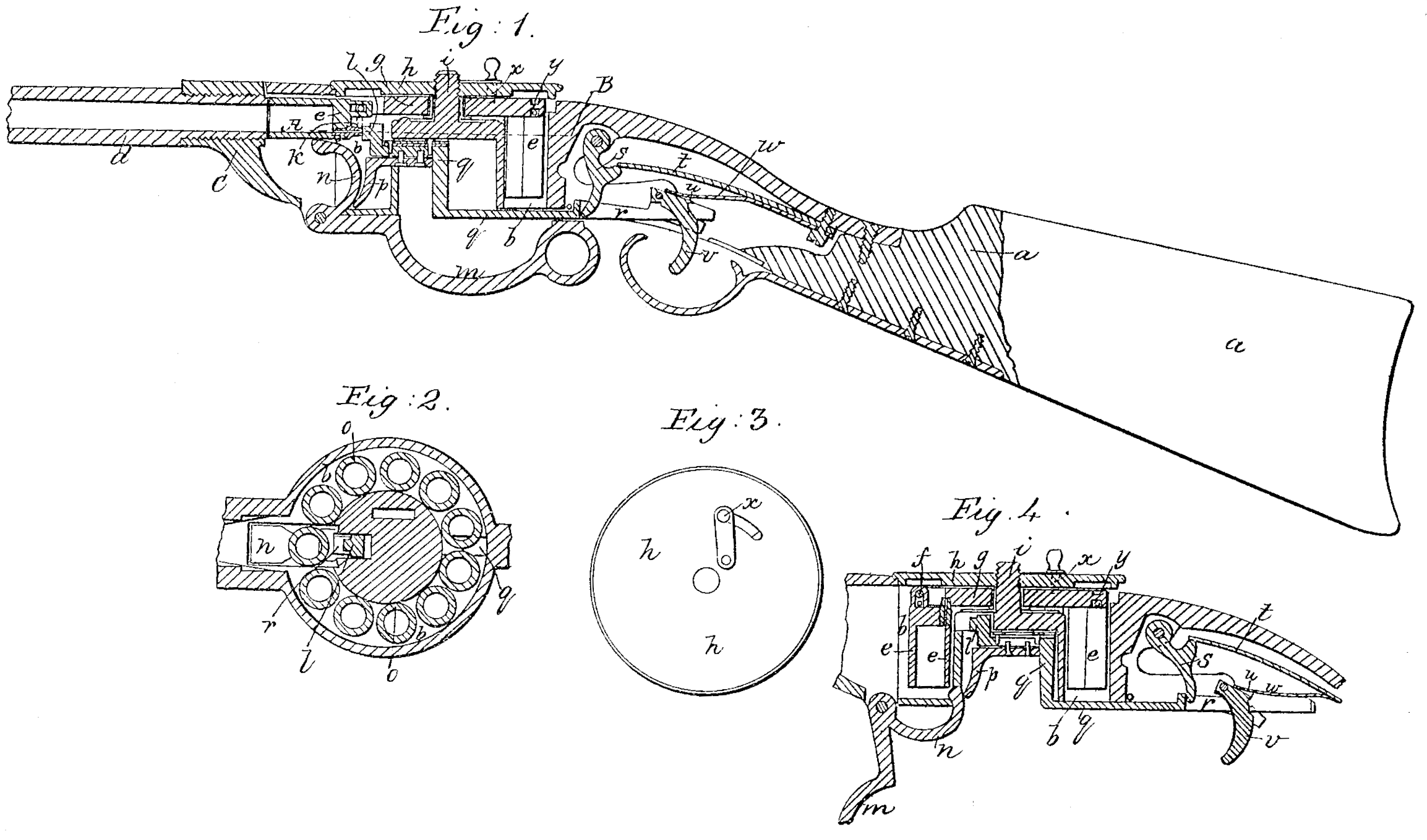
Figure 1 is a central longitudinal vertical section of a gun constructed on my improved plan. Fig.2 is a transverse vertical section of the same taken in the plane of the line A B, Fig.1. Fig.3is a detail view to be hereinafter referred to. Fig. 4 is a detail vertical section Showing the gun cocked.
In my improved gun the charges are inserted in a series of short barrels or tubes arranged in a box or cylinder. These tubes instead of being stationary are attached by a pivot or hinge to a revolving plate and hang in a vertical position from this plate until the gun is to be discharged when one of the tubes is elevated by a lever which also cocks the gun and brings the tube into a horizontal position in a line with and close to the end of the barrel of the gun all the other tubes at the time of the discharge retaining their vertical position. After the discharge the first tube is lowered to its original position and the plate to which the tubes are attached is then revolved sufficiently to bring the next tube in succession into the proper position to be elevated as before. By this arrangement each tube which is to be discharged is at the moment of firing removed a long distance from the remaining tubes, being in an elevated horizontal position, while the others hang down in a vertical position. Hence there is no possibility of communicating the fire from the tube discharged to the others and the products of combustion cannot escape and foul the mechanism in the cylinder.
a a in the drawings represent the stock of the gun.
b b is a cylindrical chamber or box into a projection a of which the gun-barrel d is screwed.
e e &c., are a series of short tubes in which the charges are placed. These tubes are attached by a pivot or hinge f to a plate, g, which is secured to the covering-plate h of the cylinder b b in such a manner as to turn independently of the same. The plate h which thus sustains the revolving plate g and the tubes e e of which there can be any number, are screwed onto the screw-shaft i of the cylinder b b, the tubes e e hanging in the said cylinder in a vertical position as shown in the drawings.
The gun is loaded by unscrewing the top plate h when the said plate and the tubes e e can betaken out all at once. The charges are then inserted in the tubes e e and percussion-caps placed on the cap-tubes k k &c. The plate h with the tubes e e, is then screwed onto the screw-shaft i, the tubes e e, containing the charges being then in a vertical position in the cylinder b b as before explained.
When the gun is to be discharged one of the tubes is raised into a horizontal position on a line with and close to the gun-barrel and so as to bring the cap-tube k on a level with the hammer l the operation of which will be presently explained by means of a lever m n, turning on a pivot at o the short arm n of the lever when the long arm m is in the position shown in Fig 1 holding the tube up close to the gun-barrel as clearly shown in Fig 1. When the plate 1 with its tubes is first screwed into the cylinder b b the short arm n of the lever m n is drawn back into the position shown in Fig.4 so as to present no obstruction to the revolution of the tubes in the cylinder while the plate l is being screwed onto the shaft i.
The gun is cocked by means of the lever m n as shown in Fig 4 the short arm n of the lever pressing against the cam-projection p of the right angular sliding bar q q to which the hammer l is attached the projection r of which abuts against a notched pawl, s, upon which a bent spring, t, presses as shown in Fig.1. The sliding bar q q is thus forced back until a notch in the same passes beyond the pawl u of the trigger p, when the said pawl u is forced into the notch of the sliding bar q q by a bent spring, w and thereby holds it and the hammer l in the position shown in Fig 4 ready for action.
The gun is discharged by pulling the trigger v which is disengaged from the notch of the sliding bar q q,which is immediately retracted by the action of the spring t, thereby forcing the hammer l against the percussion-cap in the tube e as shown in Fig 1 and discharging the gun.
The short arm n of the lever m n can be forced back so as to allow the tubes e e to be revolved in the cylinder b b without cocking the gun by simply pressing on the trigger while the sliding bar q q is being forced back, so as to prevent the pawl u of the trigger from engaging with the notch of the bar q q. After the first tube e e has been discharged it is lowered into a vertical position by the lever m n when the next tube in succession is brought into the projecting portion c of the cylinder b b by means of the revolving plate ? which is turned the requisite distance by means of a stud x attached to the top plate h as shown in Fig.3, which stud projects through the slot y of the plate h into proper holes formed in the revolving plate g at the end of each tube e. As the plate g turns independently of the top plate, h, the tubes can be revolved one notch at a time, so as to bring each tube in succession into the projecting portion c of the cylinders b b in readiness to be raised into a horizontal position and in communication with the gun-barrel by the stud x which as fast as the plate g is turned is lifted from one notch or hole of the same and inserted in the next.
It will be evident that there are a variety of modes which can bead opted for turning the revolving plate with its tubes e e and that though eleven of these tubes are represented in the drawings a larger or smaller number may be used if desirable the tubes when used for carrying shot being somewhat longer than here represented.
From the foregoing description it will be seen that by so attaching the tubes to the revolving plate as to admit of their being separately brought into a line with the gun-barrel while the others remain in a vertical position, there is no possibility of communicating combustion to the charges in those tubes, as the tube which is elevated forms nearly a continuous barrel with the gun-barrel itself and at the time of discharge is removed a great distance from the others.
Having thus described my improvements, what I claim as my invention and desire to have Secured by Letters Patent, is—
1. So attaching the tubes or short barrels in which the charges are placed to a revolving plate as to admit of their being separately and successively elevated into a horizontal position in a line with and so as to form a continuation of the gun-barrel while the others retain a vertical position as hereinabove set forth and for the purposes specified.
2. The lever m n arranged and operating as hereinabove described for elevating and lowering the tubes which hold the charges and for cocking the gun as above set forth.
EDMUND H. GRAHAM.
Witnesses:
John M. Goodwin,
E. H. McKenney