
US 12189
UNITED STATES PATENT OFFICE.
JOSHUA STEVENS, OF CHICOPEE FALLS, MASSACHUSETTS , ASSIGNOR TO TEE MASSACHUSETTS ARMS COMPANY.
IMPROVEMENT IN REPEATING FIRE-ARMS.
Specification forming part of Letters Patent No. 12,189, dated January 2, 1855.
To all whom it may concern:
Be it known that I, Joshua Stevens, of Chicopee Falls, in the county of Hampden and State of Massachusetts, have invented certain new and useful Improvements in Repeating Fire-Arms; and I do hereby declare that the same is fully described and represented in the following specification and accompanying drawings, letters, figures, and references thereof.
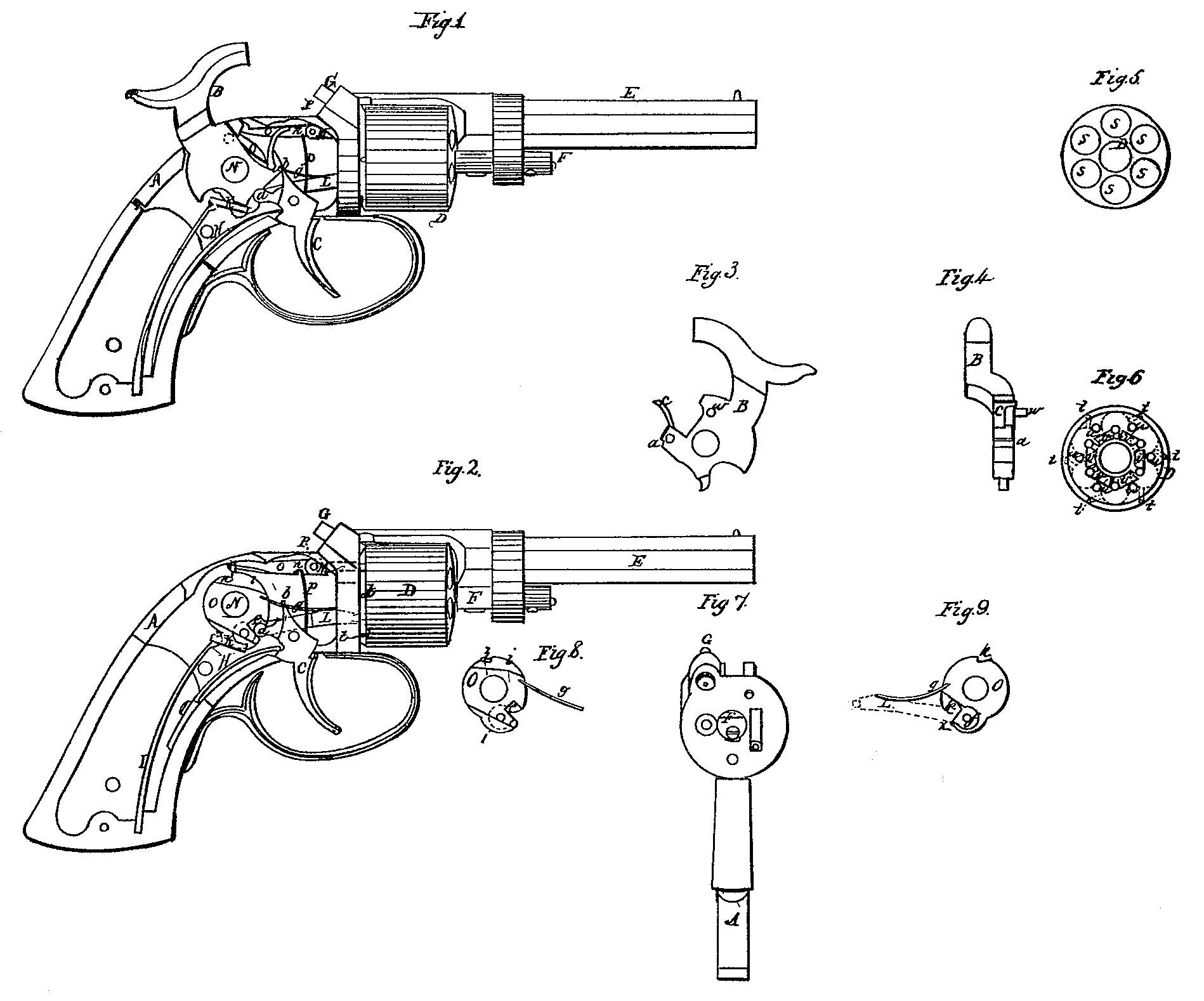
Of the said drawings, Figure 1 denotes a side elevation of a revolver-pistol constructed in accordance with my invention, one of its lock-plates being removed in order to exhibit the internal construction of the lock, and the hammer being shown as elevated. Fig. 2 exhibits a view of the lock as it appears when the hammer is removed from it. Fig. 3 is an inner side view of the hammer. Fig. 4 is a front edge view of the same. Fig. 5 is a front end view of the rotary cylinder. Fig. 6 is a rear end view of the same. Fig. 7 is a front end view of the breech-plate of the lock and the journal on which the cylinder revolves.
In these drawings, or in such of them as the same may be shown, A represents the lock-case or handle of the fire-arm or pistol; B, the percussion hammer or cock; C, the trigger; D, the rotary cylinder or magazine; E, the barrel; F, the journal on which the rotary cylinder D is supported and revolved. G is the percussion-nipple; H, the trigger-spring; I, the mainspring, connected to the hammer by means of a stirrup, K; L, the lever for turning the magazine or cylinder D. M is the bolt of the said cylinder.
The hammer is provided with a small notch, a, for the catch part b of the trigger to take into in order to set said hammer to a full-cock. When the hammer is made to actuate a “Maynard primer” (for which the fire-arm delineated in the drawings is prepared) it may be provided with a small impelling-pawl, c, arranged upon it as seen in the drawings. This, however, forms no part of my invention. A stationary journal, N, for the hammer to rotate upon, is placed in the lock-case, and by the side of this hammer is a tumbler, O, which rotates freely on the journal N, and is moved thereon by means of an arm, d, projecting from the trigger and made to work into a notch, e, formed in the tumbler, as seen in the drawings, and particularly in Figs, 8 and 9, which are views of opposite sides of said tumbler. To this tumbler the turning-lever L. may be jointed, the end of the lever being placed within a recess,f, formed in the tumbler, as seen in Fig. 9, the said recess being provided with a bearer, x, against which the lever L. rests when and so that it may be elevated by the tumbler. In Fig. 9 the lever L is represented by dotted lines.
A spring, 9, projecting from the tumbler rests on the upper side of the lever I and serves to press down the front end of the lever at proper times. The upper part of the tumbler is formed with a catch or notch, h, and a cam, i, which operates on the tail-hook of the bolt M for the purpose of withdrawing it and the bolt, the said bolt being moved forward by means of a spring, P, projecting upward from the lower part of the lock-case and made to enter a small recess or notch, n, formed in the tail-hook O,such tail-hook being jointed to the bolt, so as to be capable of moving freely in a vertical plane. During the rotation of the tumbler by the trigger the catch h will be carried into contact with the part r of the tail-hook and will draw back the tail-hook and its bolt until the cam i, acting against the tail-hook, shall force the part r entirely above the catch h, which taking place the bolt will be set free, so as to be moved forward by its spring, the action of which is such as not only to move the bolt, but to press its tail-hook downward toward the tumbler. By arranging the notch n below the joint p, as seen in the drawings, the spring is caused to operate upon the tail-hook, so as to depress it in the manner as specified.
The cylinder D, being provided with a series of charge-chambers, s s s, is to have imparted to it such an intermittent rotary motion as will bring the touch-holes of its several chambers (such touch-holes being represented in Fig. 6 at t t t, and their directions being therein represented by dotted lines) successively into line with the bore of the barrel. The rear end of the cylinder is formed with locking-recesses u u, and a ratchet or turning-cams, v v v, arranged as seen in Fig. 6, they being constructed and made to operate with respect to the bolt and turning-lever essentially like those in common use in many pistols having revolving magazines, cylinders, or a series of barrels. During the reciprocating rotary movement of the tumbler, produced by the movement of the trigger and the spring H thereof, the turning lever or finger L will be moved forward and upward against the bearing-face of a tooth of the ratchet and be subsequently drawn backward away from the ratchet, while the spring g will force it downward, so as to cause it to pass over the next succeeding tooth of the ratchet. While being moved by the tumbler the bearer x comes in contact with the turning-lever and forces it upward.
I would further remark that when the turning-lever L is forced against a tooth of the ratchet during the time the cylinder is being revolved there is to such lever no forward motion, such as would tend to crowd the cylinder in a longitudinal direction against the barrel or its front support. This action of the lever is very important, and prevents any of that serious friction of the cylinder against the barrel or front bearing which is often produced by a spring or a pawl so acting as to press the cylinder forward while in the act of turning it around.
From the rear side of the hammer there projects a cam-pin, w, which should be so made and applied that while the hammer is in the act of descending it may so act against the tail-hook o as to elevate or keep elevated the said tail-hook so far above the catch h of the tumbler that such catch may pass by and not act on the part r in case the movement of the trigger is so rapid as to render the cylinder liable to be rotated before the charge fired by the action of the hammer has left its chamber in the cylinder. In this case, or when the trigger is moved back with too great rapidity or without effecting any rotation of the cylinder, it must be suffered to again move forward before it can produce such a movement of the cylinder. This done, during the next backward pull of the trigger, the hammer being down upon the nipple, the catch of the tumbler will so act against the tail-hook of the bolt as to draw the bolt backward and enable the turning mechanism to revolve the cylinder.
As the rapidity of back movement of the trigger should be such as to allow a charge to fully leave its chamber before the cylinder is again rotated, if we allow the locking-bolt to commence its backward movement at the instant the hammer strikes on the nipple the interval of time required to draw the bolt out of its recess in the cylinder will be ample for the explosion of the charge and its exit from the chamber. We should therefore be particular that the locking-bolt is not retracted before the hammer strikes down on the nipple.
The cam-pin eases down the tail-hook of the locking-bolt, so that it may be caught by the catch of the tumbler after or about the time the hammer has struck on the nipple, provided the movement of such catch has not been so rapid as to pass by the part r. In case the back movement of the catch has been too fast the locking-bolt will not have been withdrawn from the cylinder. Consequently no rotation of the cylinder can take place until such bolt is so withdrawn, and it cannot be withdrawn without suffering the trigger to move forward and again pulling it backward. Were it not for the cam-pin or some equivalent element a too rapid rearward movement of the trigger would be likely to cause the bolt to be drawn and the cylinder rotated before a charge after explosion could fairly leave its chamber.
The herein described and represented arrangement and combination of the trigger and its spring, a rotary tumbler separate from the trigger and moving on a separate pin or journal, the turning mechanism, and the locking or unlocking mechanism, afford important advantages in the within-described repeating fire-arm provided with revolving cylinders or a series of barrels.
I am aware that by a single pull or back movement of a trigger the lock-hammer has been elevated, the cylinder unlocked and revolved, so as to bring up to the hammer the percussion-nipple of a chamber to be discharged, the cylinder locked, and the hammer set free, so as to be thrown down by its spring, these several operations having been effected in the order stated, while the restoration of the parts to their proper positions for another pull of the trigger has been produced during the return or forward movement of such trigger.
I am also aware that a rotating chambered cylinder has been combined with a lock in such manner that by the operation of lifting the hammer the cylinder has been rotated to the extent required to bring a loaded chamber in line of a barrel preparatory to a discharge of the load thereof.
I am also aware that there has been combined with a rotary cylinder and its hammer or cock, mechanism which, by the act of lifting the hammer, would cause the cylinder to be liberated or unlocked (to admit of its being rotated) and subsequently relocked, so that said cylinder may be held in a proper position during a discharge from it. I would remark that my invention operates very differently from such, as in it the hammer is not elevated by force acting through the trigger, it being only discharged by such force, and is elevated by a separate power or that of the hand of a person applied to it. This feature, however, is not new, and is found in fire-arms whose cylinders are rotated by means of power acting through their hammers. In my invention the fall of the hammer and the discharge of its chamber takes place before and not after the cylinder is rotated, so as to bring a loaded chamber into line with the barrel, such rotation following a discharge and bringing up to the priming element the next chamber to be fired. All this is accomplished by power applied to the trigger, and during one entire backward movement of it.
In my invention the unlocking of the cylinder immediately follows the discharge of the hammer or cock, the turning of such cylinder next taking place and being succeeded by the locking of it preparatory to the next fall of the hammer. With my invention, while I retain all the advantage of the hammer to be cocked by the hand or thumb of a person applied directly to it and to be maintained at cock by the trigger, so that a slight pull on the trigger will suffice to set it off, I get rid of that strain of the main-spring on the trigger which results whenever the hammer is elevated by force applied to the trigger, such strain being often productive of painful and injurious consequences. The only strain on the finger is that of the trigger-spring and the power required to rotate the cylinder.
In rapid firing it becomes desirable to have as little power as possible exerted in the elevation of the cock or hammer when it is raised by the application of the thumb directly to it. If to the power required to elevate it an additional amount of force must be brought to bear upon it in order to effect the rotation of the cylinder, this additional power, especially when a lock becomes foul, is an obstacle to rapid firing; but when such power, as in my invention, is applied through the trigger and to immediately follow a discharge the hand and forefinger are in a very favorable position to effect the rotation of the cylinder.
I do not claim jointing an impelling-pawl directly to the lower part of a percussion-hammer, so that by the reciprocating rotary movement of the hammer the said pawl may be moved against and drawn away from the ratchet of the revolving cylinder; nor do I claim jointing a lever directly to the trigger, so that by the movement of the trigger such lever may be moved against one tooth of the ratchet or drawn back over the next succeeding tooth and against a spring acting upon the rear end of the lever; but
What I do claim is—
1. The hereinbefore described and represented arrangement and combination of the trigger and its spring, a rotary tumbler separate from the trigger and moving on a separate pin or fulcrum, a turning mechanism of the cylinder, and the locking and unlocking mechanism thereof, by which arrangement and combination during and by a back-and-forward movement of the trigger the cylinder will be locked or unlocked and have an intermittent rotary motion imparted to it and the cock or percussion-hammer be actuated, essentially as specified.
2. So combining the trigger, the hammer, and the mechanism for rotating the cylinder that by a single pull on and during the back movement of the trigger the hammer shall be discharged or set free from the trigger, so as to fall on the nipple when the touch-hole of one charge-chamber of the cylinder is in connection with it, and the cylinder subsequently rotated, so as to bring up to the percussion-nipple or its equivalent the touch-hole of the next chamber of the series thereof.
3. In combination with the mechanism for turning the cylinder and that for locking and unlocking it, a cam-pin projecting from the hammer or its equivalent for preventing the cylinder from being unlocked or for locking it in case the movement of the trigger is so rapid as to render the cylinder liable to be rotated before the charge fired by the action of the hammer has left its chamber.
4. The bearer x, or its equivalent, in combination with the turning-lever L and the part or tumbler to which it is connected or jointed and by which motion is imparted to the said turning-lever, as specified, this combination attaining an important advantage, as herein before explained.
In testimony whereof I have hereunto set my signature this 21st day of November, A.D. 1854.
JOSEIUA STEVENS.
Witnesses:
J. Durell Greene,
E. W. B. Holcomb.