
US 103013
UNITED STATES PATENT OFFICE.
GEORGE W. H. CALVER, OF BURLINGTON, NEW JERSEY.
IMPROVEMENT IN REVOLVING FIRE-ARMS.
Specification forming part of Letters Patent No. 103,013, dated May 17, 1870.
To all whom, it may concern:
Be it known that I, G. W. H. CALVER, M.D., of Burlington, in the county of Burlington and State of New Jersey, have invented a new and useful Improvement in Automatic Cartridge-Ejectors; and I do hereby declare that the following is a full, clear, and exact description thereof, which will enable others skilled in the art to make and use the same, reference being had to the accompanying drawings, forming
part of this specification.
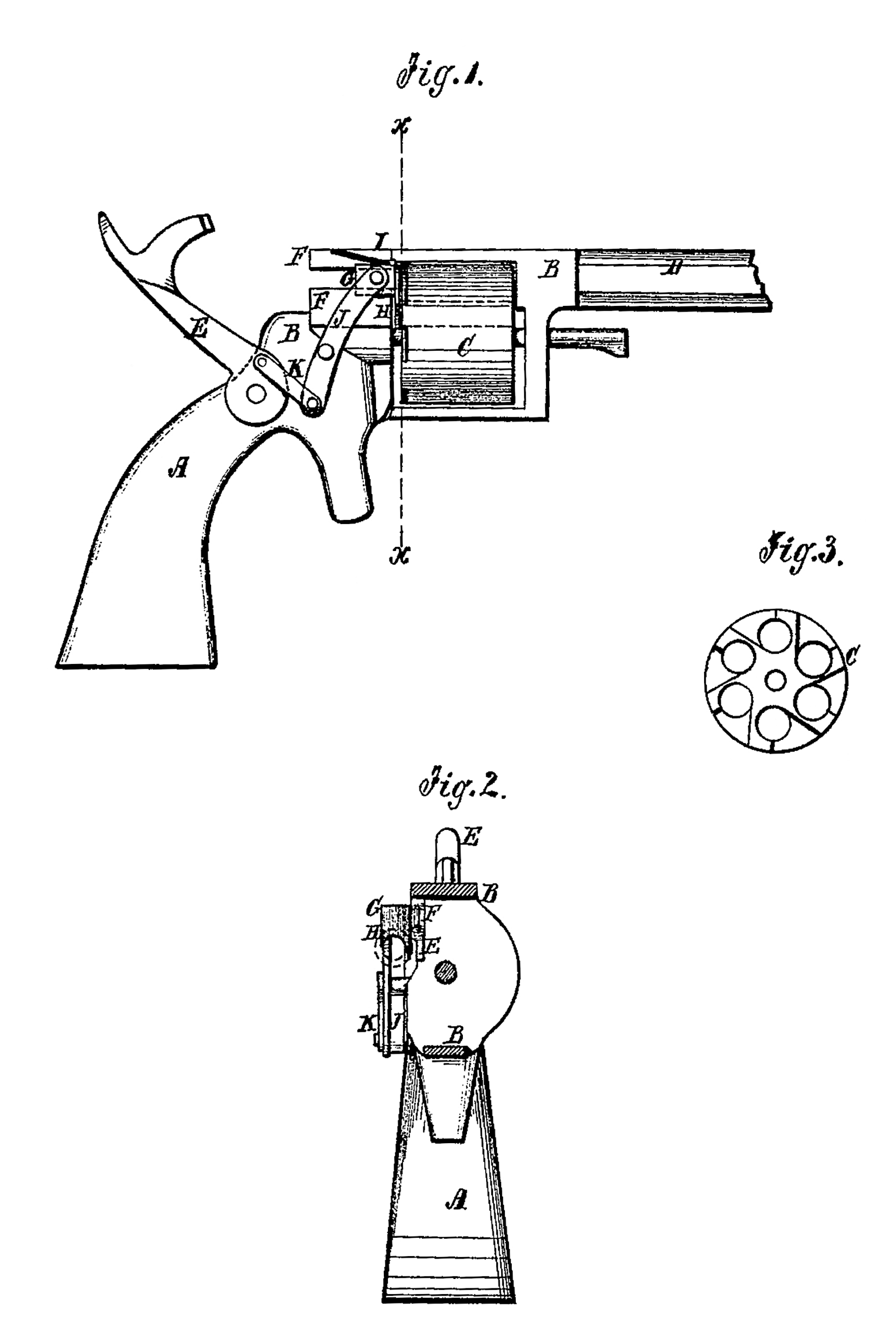
Figure 1 is a side view of a revolver to which my improvement has been attached. Fig. 2 is
a cross-section of the same, taken through the line x x, Fig. 1. Fig. 3 is a detail view of the rear end of the cylinder.
Similar letters of reference indicate corresponding parts.
My invention has for its object to furnish an improved cartridge-ejector designed for attachment to all kinds of revolving or cylinder small-arms, which shall be simple in its construction, automatic in its action, and effective in its operation; and it consists in the cartridge-ejector constructed and operating as hereinafter more fully described.
A represents the stock; B, the frame; C, the cylinder; D, the barrel; and E the hammer, about the construction of which there is nothing new.
To the frame B, at the rear end of the cylinder C, are attached or upon it are formed two
thin pieces, F, parallel with each other, to form a groove or way for the sliding block G, the forward end of which is provided with a claw, H, so formed as to fit upon the body of the cartridge-shell in front of its rim or flange, so as to draw out the said shell as the slide G is drawn rearward.
The forward edge of the claw H should be beveled or rounded off to cause it to slip over the rim of the cartridge as the slide G is pushed forward. The rear end of the cylinder C, over each chamber, should be recessed to allow the claw H to pass over the rim of the cartridge to the forward side of said rim as the block G is pushed forward.
I is a spring attached to the upper piece or strip, F, or to the frame B, in such a position as to rest upon the upper end of the claw H when the slide G is pushed forward to force and hold the claw H down upon the neck of the cartridge. The spring I is not absolutely essential, but I prefer to use it to insure the claw’s always taking hold of the cartridge-shell. The slide G is operated from the hammer E by the lever J, which is pivoted to the frame B, and the upper end of which is pivoted to the said slide G. The lower end of the lever J is connected with the hammer E by a short connecting bar or link, K, as shown in Fig.1. By this construction, when the hammer E is drawn back to cock the arm the slide G is pushed forward to grasp the shell of the cartridge last discharged, so that as hammer is thrown forward in discharging the arm the forward movement of the hammer operates the lever J, draws back the slide G, and draws out the shell of the cartridge.
It should be observed that when there is not sufficient room between the pivoting point of the lever J and the rear end of the cylinder C to admit of loading from the rear, it will be necessary to cut away a portion of the base of the frame B upon the opposite or left side of the arm to admit of loading upon that side.
Having thus described my invention, I claim as new and desire to secure by Letters Patent–
For removing the shell of a discharged cartridge from the rear of the cylinder, the slide G, claw H, lever J, and link K, in combination with the hammer of the arm, when arranged to operate substantially as hereinbefore set forth.
GEORGE W. H. CALVER.
Witnesses:
G. E. HAYS,
B. WINSLOW FIERCE.