
US 223645
UNITED STATES PATENT OFFICE.
PETER A. HOLTER, OF WORCESTER, MASSACHUSETTS.
REVOLVING FIRE-ARM.
SPECIFICATION forming part of Letters Patent No. 223,645, dated January 20, 1880.
Application filed October 25, 1879.
To all whom it may concern:
Be it known that I, PETER A. HOLTER, of the city and county of Worcester, and Commonwealth of Massachusetts, have invented certain new and useful Improvements in Revolving Fire-Arms; and I do hereby declare that the following is a full, clear, and exact description of the same, reference being had to the accompanying drawings, forming a part of this specification, and in which–
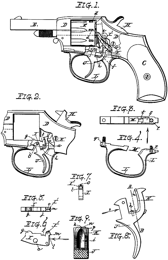
Figure 1 represents a side view of an ordinary double-action revolver with my improvements applied thereto, a portion of the side of the frame being represented broken away or shown in section to more clearly illustrate my said improvements, which are represented in the positions which they occupy when the hammer of the revolver is down. Fig. 2 represents a side view of so much of the frame of the revolver and parts connected therewith shown in Fig. 1 as is necessary to illustrate my aforesaid improvements, a section of the same being broken away, as in the former case, to illustrate the parts more clearly. In this instance said parts are represented in the positions which they occupy when the hammer is raised full-cocked, ready for firing. Fig. 3 represents a top or plan view of my improved skeleton trigger-guard when removed from the revolver. Fig. 4 represents a side view of the trigger-guard shown in Fig. 3, looking in the direction of the arrow, same figure. Figs. 5, 6, and 7 represent, upon an enlarged scale, a top or plan view, side view, and end view, respectively, of my improved cylinder-stop, the latter figure, 7, looking in the direction indicated by arrow 1, Fig. 6. Fig. 8 represents, upon the same enlarged scale, a side view of my improved trigger; and Fig. 9 represents a section on line A B, Fig. 8, looking in the direction indicated by arrow 2 of said figure, showing a side view of the upper part of the spring combined with the trigger, and by means of which the cylinder-stop is operated when the trigger is drawn back, as will be hereinafter more fully described.
My invention relates to the manner of constructing, arranging, and combining the cylinder-stop, trigger, and trigger-guard of an ordinary double-action revolver.
To enable those skilled in the art to which my invention belongs to make and use the same, I will proceed to describe it more in detail.
In the drawings, C represents the stock of the revolver; D, the frame; E, the barrel; F, the cartridge-cylinder; G, its operating pawl or lever, and H the hammer, to which is attached the said cartridge-cylinder pawl or lever G.
As the arrangement, construction, and operation of aforesaid parts may be of ordinary construction, no further description in reference to the same is here necessary.
The cylinder-stop I is pivoted to the frame D upon a pin, a, while the trigger J is pivoted upon a pin, b, which passes through the forward end of the cylinder-stop I, a hole or opening, c, being formed in the latter for the passage of said pin, and said hole c is made of sufficient size, as represented in the drawings, to allow the stop to swing up and down on its pivot a, so as to engage or disengage with the holding-notches d formed in cylinder F.
The stop I is arranged so as to bear with a constant pressure upon the surface of the cartridge-cylinder F by means of a flat or other formed spring, e, which is secured to the stop in a notch, f, formed in the rear part of said stop, and said spring produces a backward pressure upon the stop, thus forcing the forward rounded end g up, and producing, as before stated, a constant friction upon the cylinder, between the notches, when the cylinder is turned. By imparting such friction to the cylinder F it is prevented from turning too far when operated by its lever G, and thus fail of stopping at the proper position to be locked for firing, thereby obviating a great objection in revolvers as constructed prior to my invention.
In order to obtain the friction upon the cylinder, as before described, and at the same time hold the forward end of the stop so that it will not prematurely catch into notches d while producing such friction, I employ an angular slotted split spring, K, one end of which is secured at h to the trigger J; and the arrangement, construction, and operation of trigger J, its spring K, and cylinder-stop I are as follows: Upon the rear end of stop I is formed an angular or inverted V-shaped projection, I’, (see Figs. 5, 6, and 7,) while spring K is provided with an opening or slot, i, and is also split apart at its upper end, as represented at k, Fig. 9, thereby admitting it to be sprung apart for the purpose to be now explained. Supposing the cylinder-stop I and trigger J to be in the position represented in Fig. 1, with the upper end of spring K under and against shoulder l of said stop I, by now pulling backward upon trigger J the rear end of stop I is forced up and forward and the forward end down by spring K, and as spring K is forced up and forward by pulling upon trigger J, the end of said spring passes or springs out from under shoulder l, so that the corner m of projection I’ rests upon the flat part n of the spring. At this point the hammer is locked or half-cocked in the usual manner, the forward rounded end g of stop I being allowed to project up just sufficient to produce the desired friction, but allow the cylinder to turn, as before explained. If the revolver has been previously loaded and discharged, the empty cartridge-shells may now be removed from their chambers in cylinder F and new cartridges inserted in lieu thereof. If trigger J is now pulled still farther back and the arm full-cocked, ready for firing, as represented in Fig. 2, the operation moves the flat surface n of Spring K past corner m, when projection I’ is forced into slot i, thereby allowing the forward rounded end g of the cylinder stop I to spring up into one of the notches d and lock the cylinder F in the position to which it has been turned by its lever G–viz., so that one of the cartridge-chambers will correspond to and be on a line with the opening or bore of the barrel E of the revolver.
The hole or opening c in stop-piece I, while it does not interfere with the operation of said stop, prevents it from being displaced when the cylinder is removed.
The arm may now be discharged by pulling upon trigger J, and after the discharge, as the trigger and its spring are thrown back by the mainspring of the hammer, the pointed end o of projection I’ passes into the apex p of opening or slot i, which forces the two sides of spring K apart and allows the trigger to assume again the position represented in Fig.1.
The trigger-guard L is made in skeleton form, as represented in the drawings, instead of as ordinarily constructed, and it will be seen that by my construction it can be made lighter, and besides more easily manufactured, since all the cuts which fit into the frame D, with the exception of holes q and r and slots s and t, may be formed by one operation of the milling-machine, thereby economizing greatly in time as well as in material.
That the results above stated follow as a result of this part of my invention will be apparent to those skilled in the art to which my invention belongs.
In the old and common style of trigger guard a slot had to be cut out for the trigger to work in, while in my skeleton form the opening M is extended entirely through the guard, and in this opening the trigger works.
In practice, if desired, l contemplate making the frame D with small rounded projections or ears, to extend down on each side of the trigger and the opening M in the trigger-guard. Having described my improvements in fire-arms, what I claim therein as new and of my invention, and desire to secure by Letters Patent, is–
The combination, with cylinder F and trigger J, of stop-piece I, provided with the projections g I’, of slotted spring K, and spring e, said parts being constructed and relatively arranged substantially as and for the purposes set forth.
PETER A. HOLTER.
Witnesses:
THOS. H. DODGE,
EDWIN E. MOORE.