
US 301180
UNITED STATES PATENT OFFICE.
WILLIAM TRABUE, OF LOUISVILLE, KENTUCKY.
REVOLVING FIRE-ARM.
SPECIFICATION forming part of Letters Patent No. 301,180, dated July 1, 1884. Application filed November 1, 1883. (No model.)
To all whom, it may concern:
Be it known that I, WILLIAM TRABUE, a citizen of the United States, residing at Louisville, Kentucky, have invented new and useful Improvements in Revolving Fire-Arms, of which the following is a specification.
My invention relates to certain improvements in revolving fire-arms, and particularly to that class in which the cylinder with its base-pin is swung out laterally from the center of the barrel, and supported when swung out wholly at its forward end.
My invention has for its object to provide a revolver thus constructed with novel means for effectually ejecting the empty shells, and with novel means for locking the swinging portion of the frame, when the cylinder is returned to its place behind the barrel; and with these ends in view my invention consists in the novel features of construction herein after described in detail and specifically claimed.
In order that those skilled may know how to make and use my improved revolver, I will proceed to describe the construction and operation of the same, referring by letters to the accompanying drawings, in which–
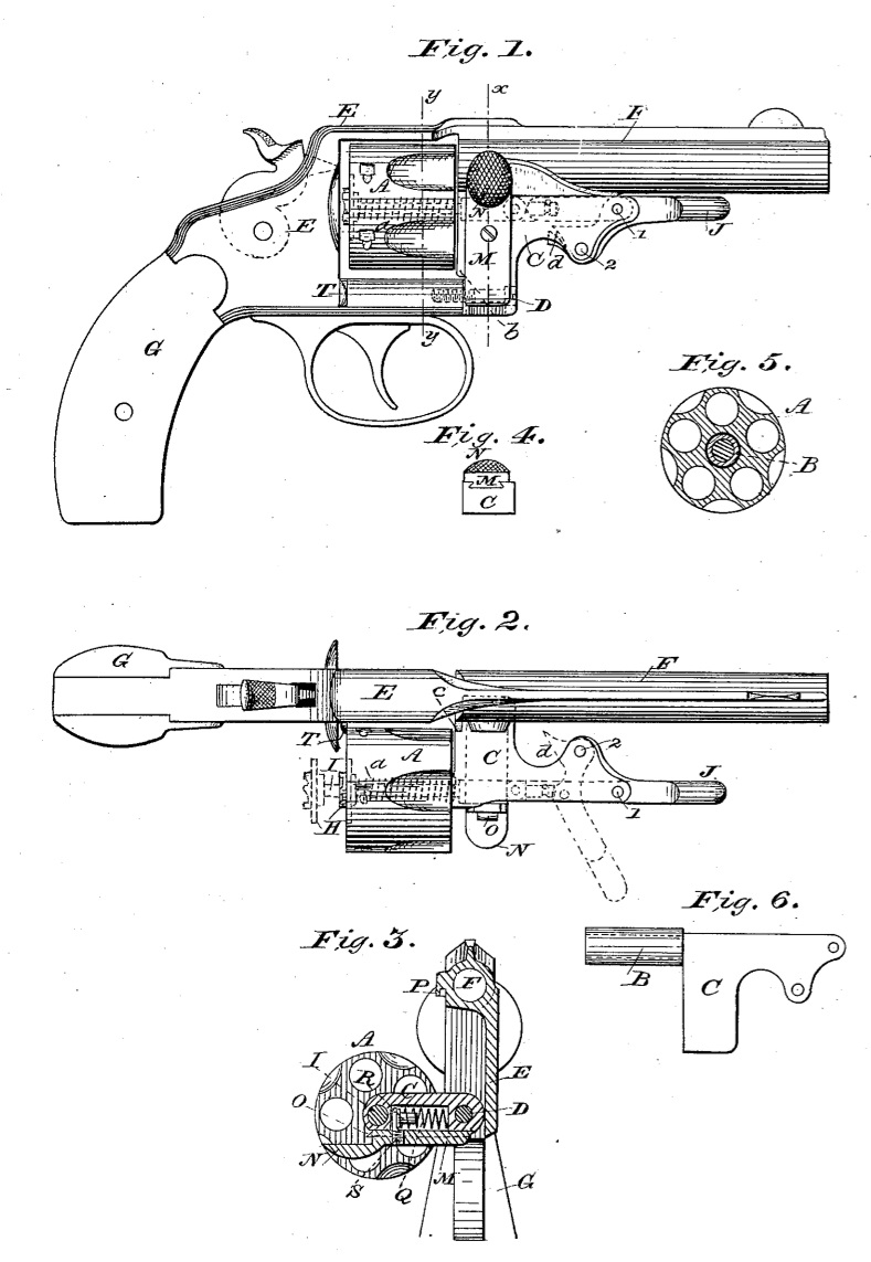
Figure 1 is a side view of a revolver embodying the features of my invention. Fig. 2 is a top view of the same with the cylinder and the swinging portion of the frame swung out laterally. Fig. 3 is a cross-section taken on the line x x of Fig. 1. Fig. 4 is a detail bottom view of the vertically-sliding spring locking plate. Fig. 5 is a cross-section at y y of Fig. 1. Fig. 6 is a detached side view of the swinging frame-piece.
Similar letters denote like parts in the several figures.
Those parts which are shown and are not specifically described in this application form the subject-matter of other applications filed by me simultaneously with this, and designated “B’ and “C.” A in this case represents the revolving cylinder, which is adapted to rotate upon the rear tubular extension of the swinging portion C of the frame, (as shown at cross-section at Fig. 5.) The swinging portion C of the frame is pivoted or hinged, as shown at D, to the forward end of the frame proper, E, in which is suitably fixed the barrel F and stock or handle G. The ejector H is connected with a rod, I, passing centrally through the cylinder and the tubular bearing B, and is connected pivotally at its forward end to a link, the opposite end of which is similarly connected at 1 to an arm or lever, J, which is of the form shown in dotted lines at Fig. 1 of the drawings. The lower extension of this lever J is pivoted at 2 to the swinging portion C of the frame, and when the frame C and cylinder are swung out into the position shown at Fig. 2 the lever J is forced outward into the position shown in dotted lines, and the ejector is forced rearward, as clearly shown. It will be seen that by reason of this construction much greater power may be exerted in case the empty shells should be “stuck’ than could be exerted by a stiff movement of a straight rod. The ejector-rod is provided with a coiled spring a, within the axis of the cylinder, which is compressed by the rear movement of the ejector, and hence its reactionary power is exerted to return the ejector, and also the lever J, to its normal position. In returning the ejector and lever to their normal position the same are brought to a stop by the end projection, d, (see Figs. 1 and 2,) of the lever J coming in contact with the inner side of the frame C.
I have not described in detail the connection of the ejector-rod with the link and lever, by which the necessary rotary movement of the ejector is provided for, as that forms a part of the subject-matter of Case B, filed simultaneously with this, and heretofore referred, to, the purpose of this application being to cover the broad idea of a toggle or lever movement in connection with a laterally-swinging cylinder to effect the ejection of the empty shells.
The swinging frame C, I have shown as hinged to the forward end of the frame proper by a screw, D; but in practice I propose employing the construction shown and described in another application filed simultaneously with this, and designated as “Case C.”
In order that the cylinder in its outward movement may be arrested at the proper point, the lower edge of the rear portion marked b of the swinging frame C is adapted to come in contact with the side of the front end of the frame E, as clearly shown at c, Fig. 2, when the cylinder is in the position shown at Fig. 3.
In order that the swinging portion C of the frame may be properly locked to the frame proper or to the barrel, I provide a vertically reciprocating plate, M, which moves in a dovetail groove in the frame C, as clearly shown at Fig. 4. This plate has a roughened thumb portion, h, by which it is operated, and a lip, O, which moves into a suitable keeper-slot, P, at the side of the frame or barrel, as clearly shown at Fig. 3, and the plate M is forced into proper position for locking by means of a coil spring, Q, and block R, which is rendered operative through the medium of a short screw-bolt, S, passing through the plate M and into or over the block R. When the lock is released and the cylinder is thrown outward, as seen at Figs. 2 and 3, the cylinder is supported against any backward movement and braced against the action of the ejector by a short projection, T, (see Fig. 2,) extending sufficiently far laterally to embrace the rear face of the cylinder.
Having described the construction and operation of my improved revolver, what I claim as new, and desire to secure by Letters Patent, is–
1. In combination with the rigid frame E and laterally-swinging frame C, upon which is 1supported the cylinder A, the ejector-rod connected by a link to a lever-arm, J, pivoted to the frame C below the plane of the movement of the ejector, substantially as and for the purpose set forth.
2. In a revolving fire-arm, the combination, with the swinging frame C, having a dovetail groove in the side thereof, and the rigid frame E, provided with the slot P, of the spring-actuated sliding plate M, having dovetail tenon, and provided with milled button N, all substantially as described.
3. In a revolving fire-arm, the combination, with the swinging frame C and cylinder A, connected as described, of the rigid frame E, having the projection T arranged to bear against the said cylinder when it is swung out, and secure it against longitudinal movement during the operation of the ejector, substantially as described.
In testimony whereof I have hereunto set my hand in the presence of two subscribing witnesses.
WILLIAM TRABUE.
Witnesses:
JAMES TRABUE,
A. H. ROBINSON.