
US 301181
UNITED STATES PATENT OFFICE.
WILLIAM TRABUE, OF LOUISVILLE, KENTUCKY.
REVOLVING FIRE-ARM,
SPECIFICATION forming part of Letters Patent No. 301,181, dated July 1, 1884.
Application filed November 17, 1883. (No model.)
To all whom, it may concern:
Be it known that I, WILLIAM TRABUE, a citizen of the United States, residing at Louisville, Kentucky, have invented new and useful Improvements in Revolving Fire-Arms, of which the following is a specification.
My invention relates to certain improvements in that class of revolving fire-arms in which the cylinder is swung out laterally and has its bearing-support at the front end, as specially referred to in another application, designated as “Case A,’ and filed by me simultaneously with this.
My present invention relates particularly to the special construction and arrangement of the ejector rod and operating-lever, by means of which the former is permitted to freely rotate with the cylinder; and my invention also has for its object to provide a means for positively locking the rear end of the cylinder in proper alignment with the barrel at or before the discharge; and, with these ends in view, my invention consists, first, in connecting the forward end of the ejector rod or stem with the rear end of the link, by which it in turn is connected to the operating-lever (described in Case A) in such manner that the ejector-rod is free to rotate, and may be readily disconnected from the link; and my invention consists, secondly, in providing a bolt adapted to be operated positively by a pull on the trigger, and which shall-be thereby moved upwardly and across a curved groove in the breech to lock therein a projecting teat on the rear end of the cylinder, whereby the latter is locked at the rear end against lateral movement, as will be hereinafter fully described.
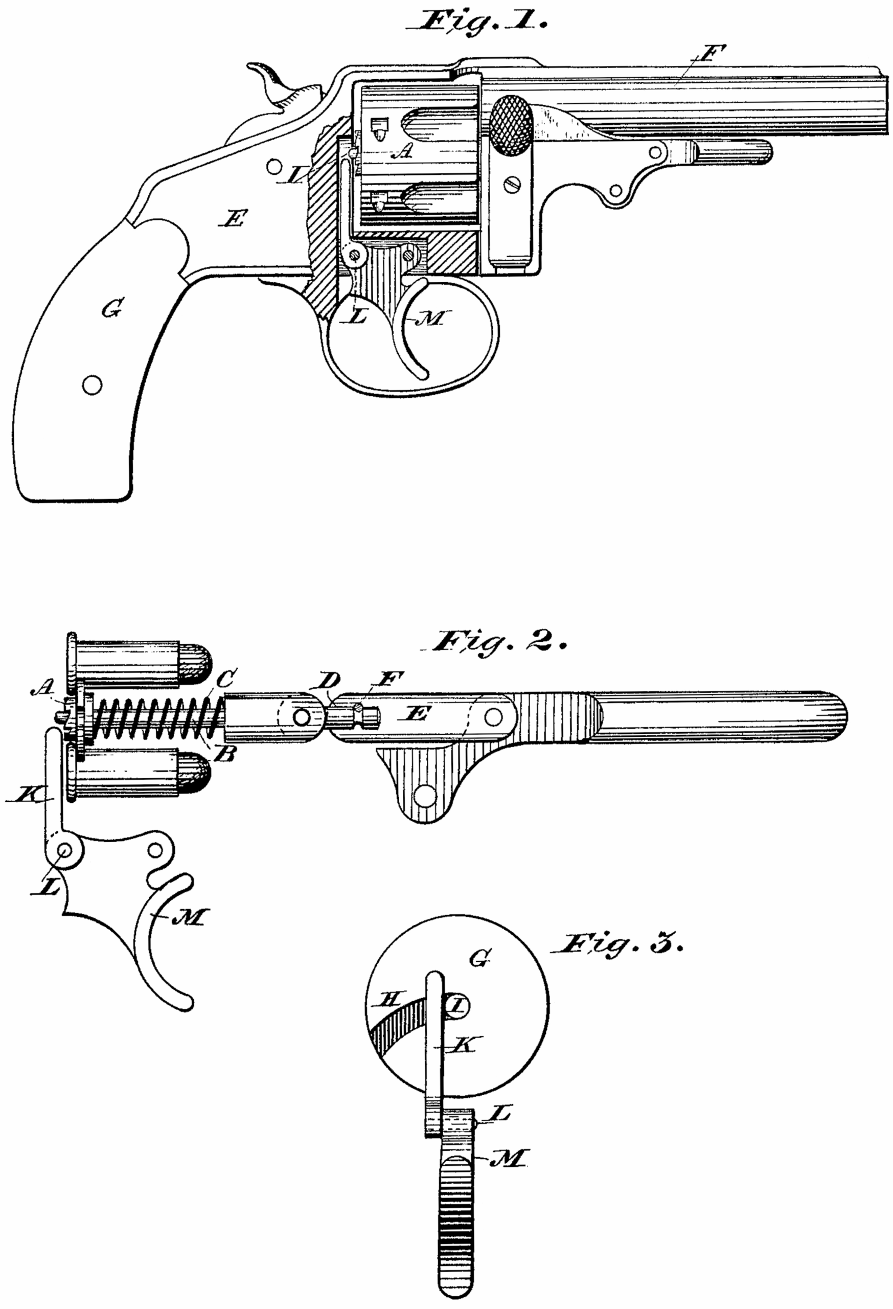
In the accompanying drawings, Figure 1 is a side view of a revolver such as is described in my other application, “Case A,” and embodying my present invention. Fig. 2 is a similar view of the ejector and its operating mechanism, showing also the trigger and locking-bolt; and Fig. 3, a front view of the breech, and showing the curved channel and teat, on rear of cylinder, and the locking bolt, &c.
Similar letters denote like parts in the several figures.
A. represents the ejector disk or plate with its centrally-arranged rod or stem B and retaining-spring C, which may be arranged in any suitable manner. The forward end, D, of the stem. B is formed with an annular groove as clearly shown at Fig. 2, and is adapted to enter centrally the rear end of a link, E, and secure against longitudinal movement therein by a transverse rivet, F, whereby the said stem is free to rotate within the end of the link, so that the ejector and its stem may revolve with the cylinder. The link E is pivoted to the bell-crank lever or arm in the manner shown and described in the application hereinbefore referred to, and to which reference is made for a full understanding of the same.
G represents the front or face of the breech in rear of the back end of the cylinder, and H is a curved channel formed in the face of the breech, into which projects a teat, I, (see Figs. 1 and 3,) projecting rearward from the center of the cylinder. This teat comes in contact with the end of the channel H at the moment the cylinder is in proper axial alignment with the barrel, and when its front end has been locked by the locking plate or bolt described in Case A; and in order that the rear end of the cylinder shall be positively secured in this position at the time of firing the weapon, I provide a short vertically-reciprocating bolt, K, seated within a vertical groove in the face of the breech and intersecting the curved channel H at such point. that when the said bolt is in its upward position, as seen at Fig. 3, it will confine the teat I in place. The lower end of the bolt K is pivotally connected, as shown at L, to the upper rear end of the trigger, and obviously, as the trigger is pulled to discharge the weapon, the bolt K is forced upward and securely locks the cylinder.
What I here claim, and desire to secure by Letters Patent, is–
1. In a revolver in which the cylinder swings laterally outward upon a pivot-bearing at the front end, as described, the ejector-stem having its forward end provided with an annular groove and secured in position within the end of a link, E, by means of a pin, F, in combination with the lever adapted to operate the same, substantially as and for the purpose set forth.
2. The combination with the cylinder adapted to swing laterally outward, and provided with a projecting teat, I, at the rear end, the curved channel H and vertically-reciprocating bolt K, connected to the trigger M, substantially as shown whereby the rear end of the cylinder is locked before firing, as hereinbefore set forth.
In testimony whereof I have hereunto set my hand in the presence of two subscribing witnesses.
WILLIAM TRABUE.
Witnesses:
JAMES TRABUE,
A.H. ROBINSON