
US 270204
UNITED STATES PATENT OFFICE.
GEORGE W. CILLEY, OF NORWICH, CONNECTICUT.
LOCK FOR REVOLVERS.
SPECIFICATION forming part of Letters Patent No. 270,204, dated January 9, 1888.
Application filed August 21, 1882. (No model.)
To all whom it may concern:
Be known that 1, George W. Cilley, a citizen of the United States, residing at Norwich, in the county of New London and State 5 of Connecticut, have invented a new and useful Lock for Fire-Arms, of which the following is a specification.
My invention relates to a lock-movement in a double-action pistol; and it consists in the peculiar construction and combination of the sickle-lever, fly-pawl, revolver-lever, and trigger.
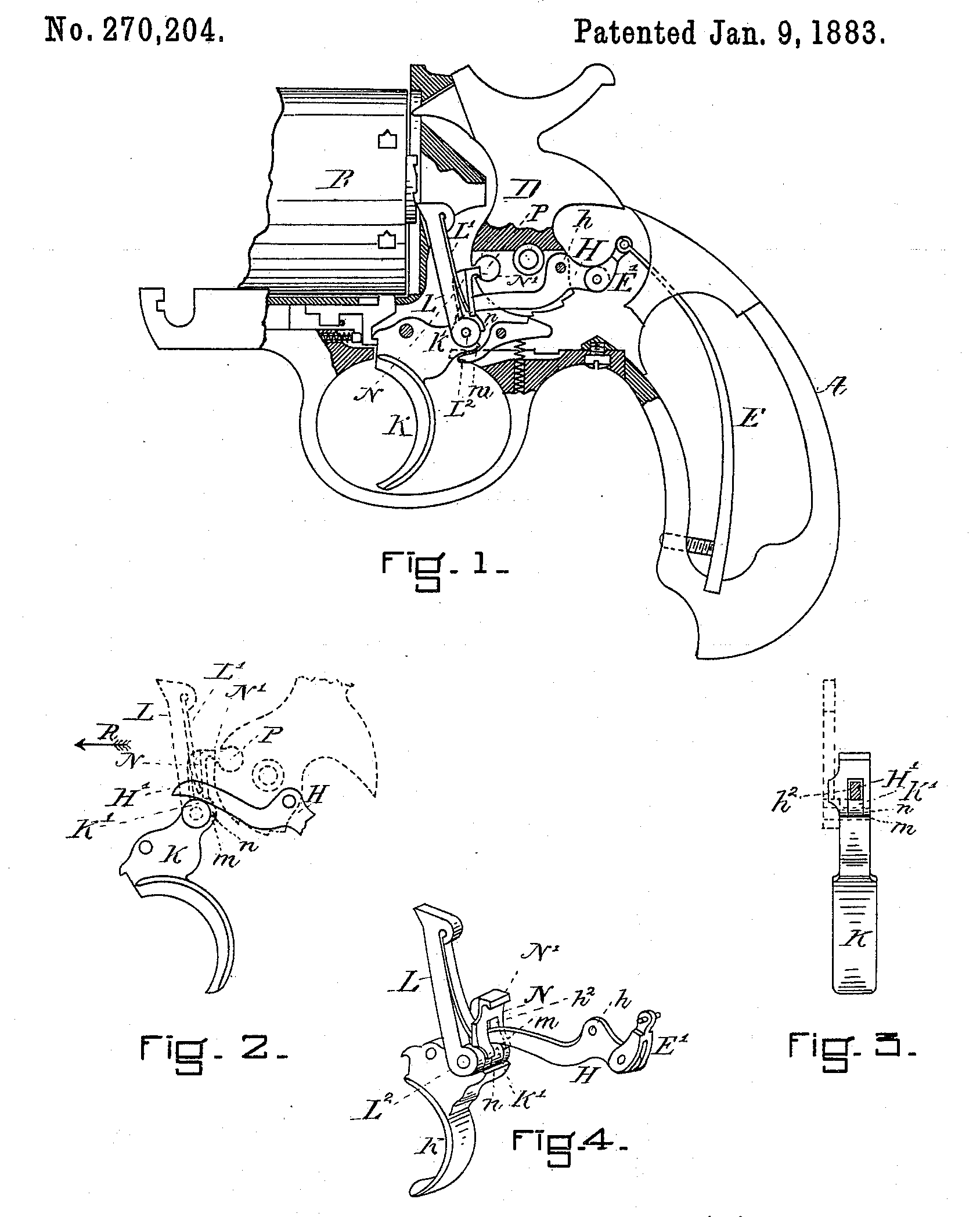
The invention is shown in the accompanying drawings, in which Figure 1 is an elevation, parts being shown in section. Fig. 2 is a side elevation of details. Fig. 3 is a rear elevation of the details shown in Fig. 2. Fig. 4 is a perspective view showing details.
A B D E, Fig. 1, represent respectively the stock, revolver-cylinder, and spring. The spring E is attached to the sickle-lever H by a link, E’. This sickle-lever H passes through a recess made in the lower part of the hammer D, and is pivoted to the hammer at h. The forward end, H’, of the sickle-lever H rests upon the rounded upper part, K’, of the trigger K, (see Figs 2, 3, and 4,) so that any movement of the trigger causes or admits of the movement of the sickle-lever. The trigger has pivoted to its upper part, K’, by the pivot L^2, the revolver lever L and the fly-pawl N, so that any movement of the trigger K will cause a corresponding movement of both the cylinder-lever L and the fly-pawl N. L’, Figs. 1 and 4, is a spring attached to the revolver-lever L, and serves to force the fly-pawl N backward, so that its hook N’ shall have a tendency to enter the catch-recess P in the hammer D, Fig. 1, except when the trigger K is drawn backward to near its limit of notion, as shown in Fig. 2, in which position the shoulder n on the fly-pawl N is in contact with the shoulder m on the trigger K, so that the fly-pawl N is forced to move in the direction of the arrow R. Fig. 2, by the backward movement of the trigger K. This movement withdraws the hook N’ from the catch-recess P and allows the hammer to give its blow. The forward end, H’, of the sickle-lever H, as has already been stated, rests upon the rounded end K of the trigger K, the fly-pawl N being recessed, as shown at h^2. Figs. 3 and 4, to admit of it, and as both the fly-pawl N and the revolver-lever L are pivoted immediately to this rounded part K’ of the trigger K, it will be understood that all of these parts— viz, the sickle-lever H, the fly-pawl N, the revolver-lever L, and trigger K— are all acted upon indirectly by the mainspring E.
I claim as my invention—
The combination of the main spring E, link E’, sickle-lever E, and trigger K K’, provided with the shoulder n, with the fly-pawl N, recessed at H’, and provided with shoulders n n, hammer D, provided with the catch-recess P, revolver-lever L, and spring L’, all operating together substantially as described, and for the purpose set forth.
GEO. W. CILLEY.
Witnesses:
E. A. Tracy,
F. M. Tracy.