
US 273335
UNITED STATES PATENT OFFICE,
FRANK H. ALLEN, OF NORWICH, CONNECTICUT.
REVOLVNG FIRE-ARM.
SPECIFICATION forming part of Letters Patent No. 273,335, dated March 6, 1883.
Application filed April 17, 1882. (No model.)
To all whom it may concern:
Beit known that I, Frank H. Allen, of the city of Norwich, county of New London, and State of Connecticut, have invented certain new and useful Improvements in Revolving Fire-Arms, which improvements are fully set forth and described in the following specification, reference being had to the accompanying drawings.
My improvement relates to that class of revolving arms known as “double-acting,” deriving their particular name from the fact that they may be used as an ordinary single-action arm or may as readily be used as a self-cocking arm.
My immediate object is to produce a double-acting mechanism which shall be simple in its construction, cheaply made in its parts, positive in its action, and as easily applied to a frame made without a removable side plate as to one having such a plate.
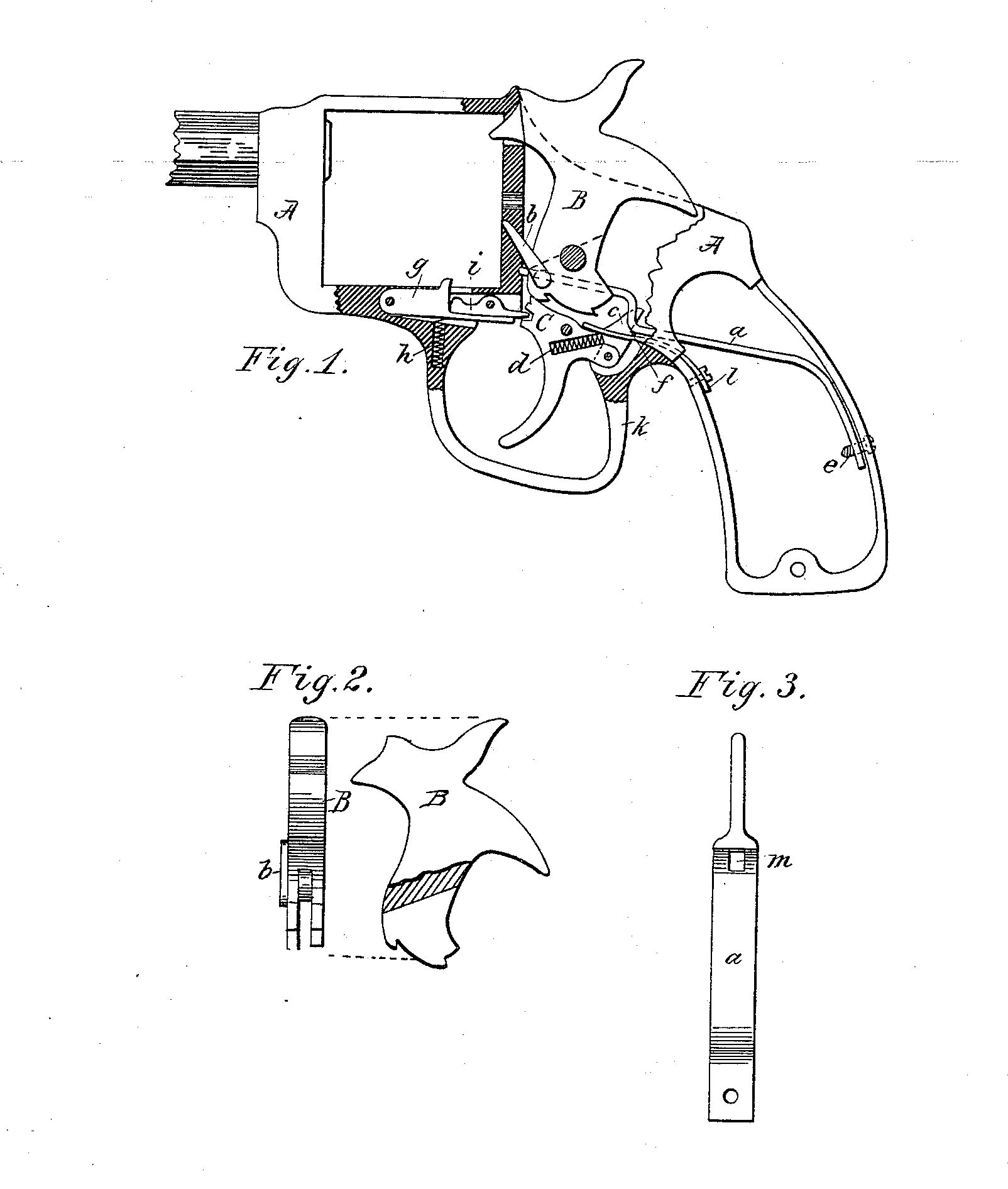
Figure 1 is a general view of my device, showing the various parts in their respective positions with the hammer down. Fig. 2 is a rear view of the hammer of my device, showing the pawl or hand for revolving the cylinder in place; also the method of slotting the hammer to receive the forward end of the mainspring. Fig. 3 is a view of my mainspring, showing its narrowed forward end and perforations to receive the lifting-latch and strain screw.
In the accompanying drawings, A represents a pistol-frame; B, the hammer; C, the trigger; a, the mainspring; b, the hand or lever by means of which the cylinder is automatically rotated when the hammer is brought to a full-cock.
In my improvement I have departed from the principles heretofore used in double-acting arms. The reservoir of power in all similar arms is of course in the mainspring. To use that power advantageously certain links, dogs, toggles, or other suitable mechanical devices have heretofore been used, by means of which the trigger, when drawn or forced back, raises the hammer, and the hammer in turn forces back the mainspring. When the hammer reaches a certain point the connecting lever or link is tripped, and the mainspring returns to its former position, pushing the hammer before it. To reach and overcome the power of the mainspring in the methods heretofore used the consequent friction of the hammer on its pivot (usually a large stud) and the friction of the several links or dogs must be met. In all such devices the hammer receives the power of the mainspring on its rear side, the hammer and spring being connected by a link or stirrup. In my device the power of the main spring is applied to the front side of the hammer with a bearing-down effect, instead of lifting, as is the case with all others. Instead of reaching the power of the mainspring through the hammer and connecting-links, I have arranged my self-cocking device so that the trigger acts directly on the mainspring, thereby avoiding all unnecessary friction, and accomplishing the desired result with fewer working parts and at less expense.
The mainspring a is provided with a suitable opening at a point over or near the rear of the trigger C, in which opening a latch, c, rests, the lower end of c being pivoted to the rear of the trigger C. The latch c is provided with a suitable notch or shoulder at a point where it intersects the mainspring. When at rest this notch is held in its place under the mainspring by a spiral spring, d, in the trigger, said spring always tending to throw the latch rearward.
The hammer B is split from the bottom about one-third its length (see Fig. 2) to receive the forward end of the mainspring, which is reduced in width, (see Fig. 3,) so that it may readily enter the hammer-slot.
The hand b in my device is identical in construction and action with the hand in arms as ordinarily made. The stud or pivot of the hand is provided with a transverse slot corresponding in position with the split hammer. Between the hand-stud thus slotted and the hammer is just room enough to receive the forward end of the main spring. When the force of the mainspring is allowed to act on the hammer it does so through the medium of the hand-stud, on which it bears. On the contrary, when the mainspring is forced upward in the act of self-cocking the arm, the spring does not bear on the hand-stud, but against the front of the hammer, pushing the hammer upward
The movement of my device as a single action is precisely the same as in revolving arms as ordinarily constructed. When the hammer is brought to a full-cock by hand, the trigger-nose drops into the half-cock or safety notch, then into the full-cock notch, holding the hammer in position until released by pressure on the trigger.
The mainspring a is secured rigidly to the frame by a screw at e, said screw also acting as a strain-screw to adjust the tension of the mainspring.
The cylinder-stop in my double-acting device forms a part of my invention. It is composed of two working parts, g and i, and a spiral spring, h, placed in the trigger-guard k, said spring acting on the piece g and holding the stop in the cylinder-notch. The smaller piece, i, extends rearward into a notch in the trigger. g and i are pivoted to the pistol-frame, the piece i working with a rocking or reciprocating motion. When the arm is cocked by hand, the trigger drops into the half-cock notch, carrying upward with it the rear end of the piece i. As the rear end of i is forced up the forward end is of course depressed, and carries with it the piece g, thereby releasing the bolt from the cylinder and allowing the cylinder to be rotated when the bolt again drops into place in the cylinder-notch. When used as a self-cocking arm, the movement of the trigger and piece i is reversed; but the result is the same with the piece g, except that it (g) does not return to its place in the cylinder-notch when the hammer comes to a full-cock, but is supplemented by the forward end of i, which, as it passes upward, enters the cylinder-notch and holds the cylinder in place while in the act of firing. When, after firing, the trigger swings forward into place, the piece i leaves the cylinder-notch and is relieved by g.
To operate my device as a self-cocking arm, force the trigger C rearward, when the lever c, by means of the notch on its rear side, will force the mainspring upward, which movement raises the hammer to a full-cock, at which point the lever c leaves its place under the mainspring. The mainspring, being no longer supported by the lever c, returns to its former position, carrying with it the hammer and exploding the cartridge.
I claim—
1. The combination of the main spring a, reduced in width at its forward end, and perforated at in to receive the latch c, the hammer B, slotted to receive the main spring a, and the hand b, said hand having its pivotal stud slotted transversely to receive and support said mainspring, as described, and for the purpose specified.
2. The combination of the split hammer B, the hand b, with its transversely-slotted pivotal stud, the mainspring a, reduced in width to enter the slot in the hammer and bear on the hand-stud, thereby imparting a downward and forward tendency to the hammer B, and the trigger C, as described, and for the purpose specified.
3. In combination with the trigger C and trigger-spring l, the two-part cylinder-bolt g i, part g being pivoted (in a suitable slot in the pistol-frame) at its forward end, and having on its upper side a projection to engage with the cylinder-notch, its rear end passing in under the piece i, and the reciprocating lever i pivoted at or near its center and so arranged with the piece g. that, when actuated by the trigger C, it (i) will, by its reciprocal movement, force the projection on the piece g out of the cylinder – notch, and, when used as a self-cocking arm, supplement, by the upward movement of its forward end, the piece g while in the act of firing, as herein before described, and for the purpose specified.
4. In a double-acting mechanism for revolving fire-arms, the combination of the following parts: the hammer B, split from its lower end to receive the mainspring, the band b, having its pivotal stud transversely slotted to support the main spring, the mainspring a, perforated at on to receive the lifting-latch and reduced in width to enter the slotted hammer, the trigger C, the trigger-spring l, and the latch c, all arranged and operated as and for the object hereinbefore specified.
FRANK H. ALLEN.
Witnesses:
C. L. Hopkins,
John E. Warner.