
US 283185
UNITED STATES PATENT OFFICE.
JAMES T. ALDRICH, OF NORWICH, CONNECTICUT, ASSIGNOR TO HIMSELF AND WILLIAM H. BABCOCK, OF SAME PLACE.
REVOLVING FIRE-ARM.
SPECIFICATION forming part of Letters Patent No. 283,185, dated August 14, 1883.
Application filed May 4, 1883. (No model.)
To all, whom it may concern:
Be it known that I, James T. Aidrich, of Norwich, in the county of New London, and in the State of Connecticut, have invented certain new and useful Improvements in Fire-Arms; and I do hereby declare that the following is a full, clear, and exact description thereof, reference being had to the accompanying drawings, in which—
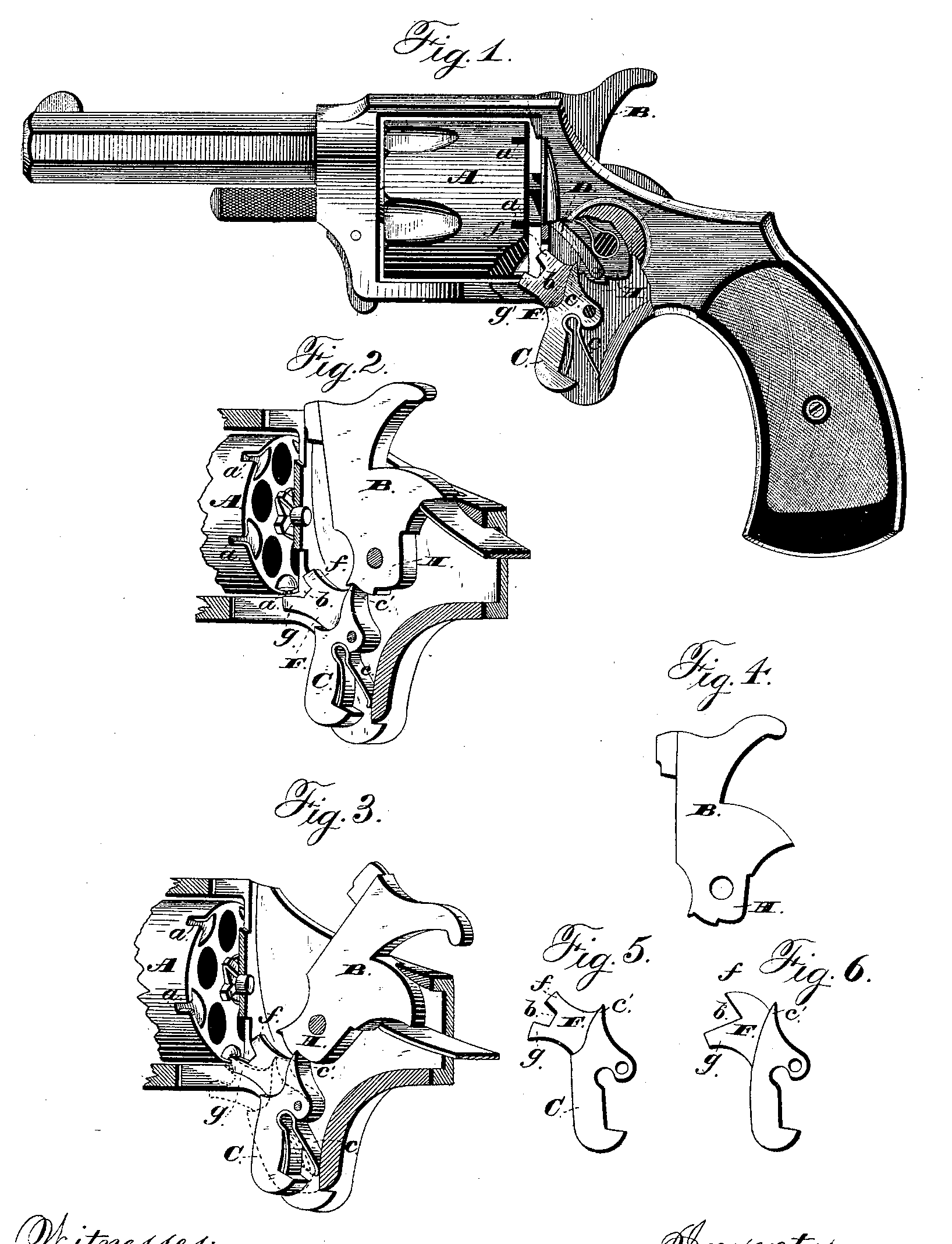
Figure 1 shows a side elevation of a pistol provided with my improvement, a portion of the frame and lock covering-plate being broken away to show the relative arrangement of the parts in operative position with the hammer down. Fig. 2 shows a perspective view of the rear portion of the cylinder and the lock-containing part of the frame, the covering-plate being broken away and the hammer shown at half-cock. Fig. 3 shows a similar view with the hammer shown at full-cock, the trigger being shown in dotted lines in the position which it takes when it is pulled in the act of firing the pistol. Figs. 4 and 5 are detail views of the hammer and trigger, respectively, and Fig. 6 is a similar view of a slightly modified form of trigger.
The object of my invention is to provide an improvement in the locking or stopping mechanism for the revolving cylinder of a pistol; and to this end it consists in the trigger provided with a projection to engage the notches in the cylinder, as hereinafter described, and specifically set forth in the claims.
In the drawings, A designates the revolving cylinder of the pistol, B the hammer, and C the trigger. The hammer has the usual rearward extension to be engaged by the end of the mainspring. The trigger is provided with a spring, c, to throw out its lower end and keep its sharpened upper end, c’, bearing against the face of the notched hammer-cam H in the ordinary way. To the side of the hammer, below the pivot-screw, is pivoted the hand D for turning the cylinder by engaging at its forward end, as the hammer is raised, with the teeth of the ratchet on the rear end of the cylinder.
The trigger is provided at its upper end with a projecting portion, F, extending forward So from its front face. This portion, as shown, is thinner than the trigger, being made of a sufficient thickness to enter freely the notches a in the rear edge of the cylinder and yet hold the cylinder without rotary play. Its front end is deeply notched, so as to leave the two projecting portions f and g, the notch being designated by b. The lower projection, g, is of such a length and shape, and so situated with relation to the trigger, as to enter one of the notches a on the cylinder when the hammer is down, and the shape of the hammer-cam allows the upper end of the trigger to be thrown back by the action of the trigger-spring. (See Fig. 1.) With the hammer in this position the cylinder will therefore be positively locked from turning by the projection on the trigger. When the hammer is raised to half-cock, the hammer-cam is of such a shape that the upper end of the trigger, as it engages the half-cock or safety-notch, cannot fall so far back, through the stress of the trigger-spring, as when the hammer is down. The lower projection just clears the edge of the cylinder and cannot be forced into the notches therein. The cylinder can then be turned freely as the edge of the same, as seen in Fig. 2, is engaged by neither of the projections f or g, but occupies a position between the two in the notch b. The hammer-cam H is of such a shape between the half and full cock notches as to keep the trigger, and consequently the projections f and g, in substantially the same position with relation to the edge of the cylinder as they have in Fig. 2. The hand D is then free to turn the cylinder the requisite distance to bring another chamber into firing position while the hammer is being raised to the full-cock notch. The bottom of this notch, against which the upper end of the trigger strikes, is nearer the center of motion of the hammer-cam than that of the half-cock notch, so that the trigger is forced by its spring farther back and the projection g is again brought up into one of the cylinder-notches, as it was in Fig. 1. (See Fig. 3.)
The pulling upon the trigger to release the hammer and fire the pistol carries the projection g and the notch b down below the edge of the cylinder and brings the projection f into the notch a, just vacated by projection f, so that the cylinder is held positively locked from accidental turning during the fall of the hammer, and the chamber is maintained properly in line with the bore of the barrel. Upon the removal of the pressure on the trigger, after the hammer has fallen into the position (shown in Fig. 1) to fire the cartridge, the projection g is by the stress of the trigger-spring thrown up again into engagement with the cylinder-notch, which now is above it and in its path. The parts are then all in position for a repetition of the action and operation, as set forth above.
As will be seen in the drawings, the rear face of the cylinder is cut away just above or within the line of notches, so that a thin rim only is left for a short distance on each side of a notch. The line of the intersection of the depression with the plane of the end of the cylinder is about the are of a circle described from outside the circumference of the end of the cylinder.
By my construction and arrangement of the locking device directly upon the trigger itself I very much simplify and cheapen the construction of the pistol, avoiding the levers and actuating-springs ordinarily employed to operate in connection. With the trigger to properly lock and release the cylinder. As the locking device is fixed directly to the trigger itself, it cannot get out of order, so as to act wrongly in relation to the movements of the parts of the firing and cylinder-turning mechanism. The pecular construction of the end of the main portion of the projection, as arranged in combination with the trigger, enables the one rigid piece to dog or lock the cylinder properly through the action of the trigger-spring while the hammer is being raised, and to positively lock said cylinder in the proper position while the trigger is being pulled and the hammer is falling and striking the cartridge.
Having thus fully set forth the nature and merits of my invention, what I claim as new is—
1. In a revolving fire-arm, the rotary cylinder provided with a series of locking-notches, in combination with a spring-pressed trigger formed with a rigid projection adapted to engage one of these notches while the hammer is down or at full-cock, and means for automatically moving the trigger, so as to unlock the cylinder during the operation of cocking, substantially as shown and described.
2. In a revolving fire-arm, the rotary cylinder provided with a series of notches, in combination with the spring-pressed trigger bearing at its upper end directly against the hammer-cam, and provided with a rigid projection adapted to normally engage one of the notches in the cylinder, substantially as and for the purpose set forth.
3. In combination with the rotary cylinder provided with a series of notches, the spring-pressed trigger formed with a rigid projection adapted to normally engage one of the cylinder-notches, and the hammer-cam so formed as to cause the trigger to be moved during the raising of the hammer, so as to disengage the projection from the cylinder-notch and leave the cylinder free to to be turned, substantially as shown and described.
4. In a revolving fire-arm, the rotary cylinder provided with a single series of locking-notches around its rear edge, in combination with the trigger provided with a projection adapted to engage one of these notches while the hammer is either down or fully cocked, and a projection adapted to engage the same during the fall of the hammer, substantially as set forth.
5. The combination of the revolving cylinder provided with a series of locking-notches, the trigger formed with the projecting portion F, notched at its front end to form the two projections f and g, the spring tending to normally keep one of said projections in one of the notches when the hammer is up or down, and the hammer-cam, so shaped as to move the trigger and carry the projection out of its notch during operation of cocking, all substantially as and for the purpose set forth.
6. In combination with the spring-pressed trigger carrying a projection to lock the cylinder, the hammer-cam cut away in front, and provided with the deep full-cock notch, and the raised portion between this and the front carrying the half-cock notch, all so arranged that the projection on the trigger engages a notch in the cylinder to lock the latter from turning while the hammer is either down or at full-cock, but is forced out of engagement therewith during the operation of raising the hammer.
7. As a locking device for the notched revolving cylinder, the hammer B, hammer-cam, H, shaped as shown, with portion cut away in front, deep full-cock notch, and raised intervening portion, in combination with trigger C, pressed by spring c, so that its upper end bear’s upon the cam, and provided with projections f and g, all substantially as and for the purpose set forth.
In testimony that I claim the foregoing I have hereunto set my hand this 23d day of April, 1883.
JAMES T. ALIORICH.
Witnesses:
Hezekiah Perkins,
William. H. Babcock.