
US 283854
UNITED STATES PATENT OFFICE.
WILLIAM. H. BLISS, OF NORWICH, CONNECTICUT.
SAFETY-LOCK FOR FIRE-ARMS.
SPECIFICATION forming part of Letters Patent No. 283,854, dated August 28, 1883.
Application filed June 20, 1883. (No model.)
To aid, whom, it may concern:
Be it known that I, William. H. Bliss, of the city of Norwich, county of New London, and State of Connecticut, have invented certain new and useful Improvements in Revolving Fire-Arms, which improvements are fully set forth and described in the following specification, reference being had to the accompanying drawings.
My improvements relate principally to a locking device by means of which an arm is rendered perfectly safe when in the hands of children or others not familiar with or competent to use the same.
They also relate to certain new and convenient forms of springs for use in “double-acting arms,” which arms are so constructed that they may be used in the ordinary manner, or may as readily be used as self-cocking arms.
My immediate object is to produce an arm which may with absolute safety be left in any convenient place about the house or office, and may be left loaded and ready for use when needed, but which cannot be discharged either by accident or design if discovered and handled, as above stated, by children.
In the several figures of the annexed drawings like letters indicate like parts.
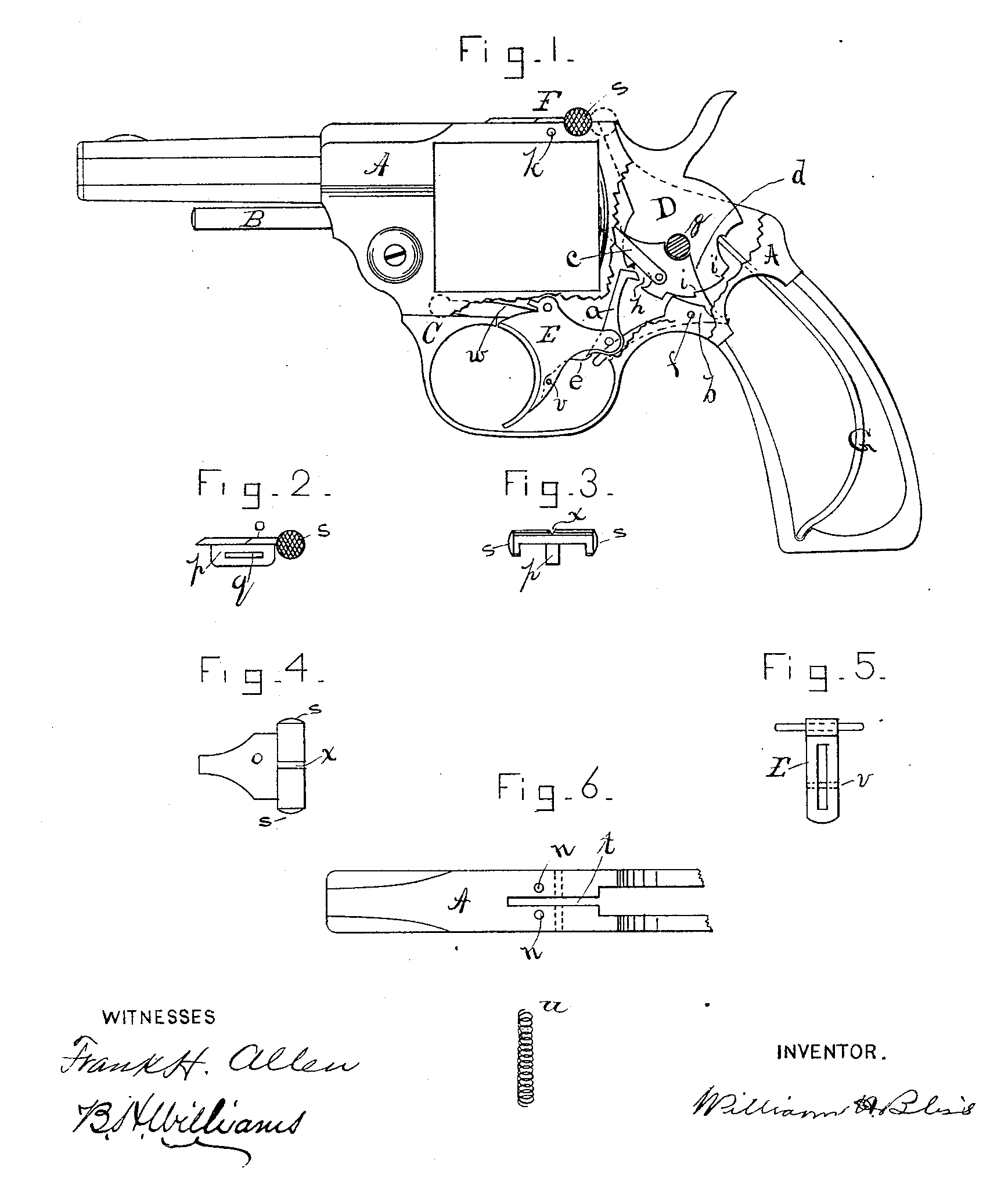
Figure I is a general view of a revolver embodying my improvements, a portion of the frame being cut away to show more clearly the various parts as they appear in their respective position. Fig. 2 is a detached side view of my locking device. Fig. 3 is a rear end view of said locking device. Fig. 4 is a top or plan view of the same. Fig. 5 is a detached rear view of the trigger of my double-acting arm, showing the groove to receive the spring which actuates the hammer-lifting arm, and also shows the pin which holds said spring in place in the trigger. Fig. 6 is a top view of a part of the revolver-frame, showing the groove to receive the locking-slide, and the friction device which acts on said slide, the spiral spring u being shown removed from hole n.
A represents the frame of my improved form of revolver; B, the base-pin on which the cylinder rotates, and C the guard which surrounds and protects the trigger E.
D is the hammer; G, the mainspring which bears on said hammer, and F is my safety-locking device. This safety device F is composed, preferably, of a single piece of metal, and is located at the top of the frame, at or near the point where the nose of the hammer intersects said frame. F is constructed (substantially as shown in the drawings) with a plate, o, which rests on the upper part of the frame, and is held in place and adapted to slide longitudinally thereon by means of a rib, p, extending downward from o, the rib p being provided with a slot, q, through which passes a pin, k, to fasten the locking device F securely in the frame. The elongated slot q allows the device to be moved backward or forward a sufficient distance to accomplish the desired result. For convenience in operating said slide I have constructed it with a projection, s, on each side, extending slightly below the frame. (See Fig. 3.) The outer surfaces or ends of s may be checked or knurled, as in Figs. 1 and 2, if desired.
To prevent the slide F from getting out of place after the arm has been locked or unlocked I insert one or more friction spiral springs in holes in in the frame A, immediately under the sliding piece. These springs, pressing upward, hold the slide in any position in which it may be left.
The frame A is recessed at t, so that the hammer, when forward and at rest, enters the frame an eighth of an inch, or thereabout.
To lock the arm, drop the hammer forward into place and slide F rearward over the top of the hammer, as indicated by the dotted lines in Fig. 1. As the hammer swings on the pivot or stud g its natural movement as it starts backward is also upward; but as the slide F is immediately over it, it of course cannot be moved until the hammer is released, which is done by sliding F forward and away from the hammer. The slide F is provided with a longitudinal V-shaped groove, x, thus forming the rear sight of the arm.
The general principle of the double-acting mechanism in my revolver is identical with that now used by several manufacturers. It is briefly described as follows: Pivoted to the rear of the trigger F is a lifting-arm a, which, by its peculiar hook-shaped upper end, is adapted to engage the hammer at the opening h for the purpose of cocking the hammer when the trigger is drawn or forced rearward. The hand which rotates the cylinder is located, preferably, on the hammer, but may, if so desired, be hung on the same pivot on which the lifting-arm a swings.
Pivoted in the frame, at f, is a sear, b, its upper surface being of such shape that it may engage the notches i and i’ on the hammer. The rear end of the sear b is forced downward by a spring, d, so that when used as a single-acting arm, or, in other words, when cocked by pressure on the hammer, the front edge of the sear drops into the usual half-cock or full-cock notches, and prevents the hammer from descending until the sear is released by pressure of the trigger against an arm of the sear, which extends forward and on one side of the trigger. The spring d, near its center, has a half-circular bend of the size and shape of the hammer-stud g. The forward end of said spring bears on the hand c, the rear end bearing on the sear b, as before stated. The yoke or half-circular bend in the center prevents the spring from moving endwise or getting out of place, but does not interfere with its working freely at either end.
My trigger-spring w is located under the guard C forward of the trigger and bears on the front of the trigger in a suitable notch, with a lifting effect to return the trigger to its proper position after the arm is discharged. In order to provide a suitable spring to act on the arm a and throw its upper end at all times rearward, I have cut in the rear side of the trigger a slot (see Fig. 5) to receive such a spring. The spring e is made of flatted steel wire bent substantially as shown in Fig. 1, the pin v passing across it, holding it securely in place, and leaving the upper end free to act upon a short arm projecting downward from the lifting-arm a.
The springs d and e constitute parts of my improvements.
Having thus described my improvements, I claim as my invention and wish to secure by Letters Patent—
l. In combination with the frame and hammer of a revolving arm, the locking device hereinbefore described, consisting of the plate o, provided with the slotted rib p, said locking device being located near the point where the top of the hammer intersects the frame, and adapted to slide on said frame, for the purpose of locking the hammer.
2. In combination with the hammer and frame of a revolving arm, the locking device having the slotted rib p, side extensions, s s, and the sight-groove x, said locking device being located near the point where the top of the hammer intersects the frame, and arranged to slide longitudinally to lock said hammer, as hereinbefore described.
3. In combination with the frame, hammer, and locking device having the slotted rib, side extensions, and sight-groove, as described, pin k, and friction-springs u, by means of which the locking slide is retained in any desired position.
4. In a double-acting mechanism for revolving arms, the combination, with the hammer, hand, and sear, of a single spring supported at or near its center by the hammer-stud, as described, one end of said spring bearing on said hand and the other end on the sear, for the purpose stated.
WILLIAM. H. BLISS.
Witnesses:
Frank H. Allen,
B. H. Williams.