
US 342507
UNITED STATES PATENT OFFICE.
GEORGE H. FOX, OF BOSTON, MASSACHUSETTS.
REVOLVER.
SPECIFICATION forming part of Letters Patent No. 342,507, dated May 25, 1886.
Application filed March 12, 1886. Serial No. 194,993. (No model.)
To all whom it may concern:
Be it known that I, GEORGE H. FOX, a citizen of the United States, residing at Boston, in the county of Suffolk and State of Massachusetts, have invented certain new and useful Improvements in Revolving Fire-Arms; and I do hereby declare the following to be a full, clear, and exact description of the invention, such as will enable others skilled in the art to which it appertains to make and use the same, reference being had to the accompanying drawings, and to letters or figures of reference marked thereon, which form a part of this specification.
This invention relates to fire-arms, more particularly revolving arms, in which the weapon is “broken,” so called, in the act of reloading; and it consists in improvements in mechanism by which the extractor is operated in order to effect the dislodgement and removal of the empty shells from the revolving cylinder.
The object of my invention is to provide an extractor-lifter which shall be operated by the breaking of the weapon, and thereby automatically induce the extractor to discharge the empty shells, and then by further swinging motion of the parts of the weapon release the lifter from the extractor and permit retreat of the latter to its normal position.
The gist of my invention is embodied in the construction of the extractor-lifter, which is radially and centrally slotted and mounted upon the pivot or joint pin connecting the stock and the barrel portion of the frame of the weapon; hence in operating the arm in the act of reloading the lifter the relative position of the lifter is changed, and it is moved eccentrically of its retaining-pin or the pivotal joint of the weapon. Furthermore, this lifter is peripherally provided with a spring, which returns it to its normal position in the act of locking the arm in readiness for use.
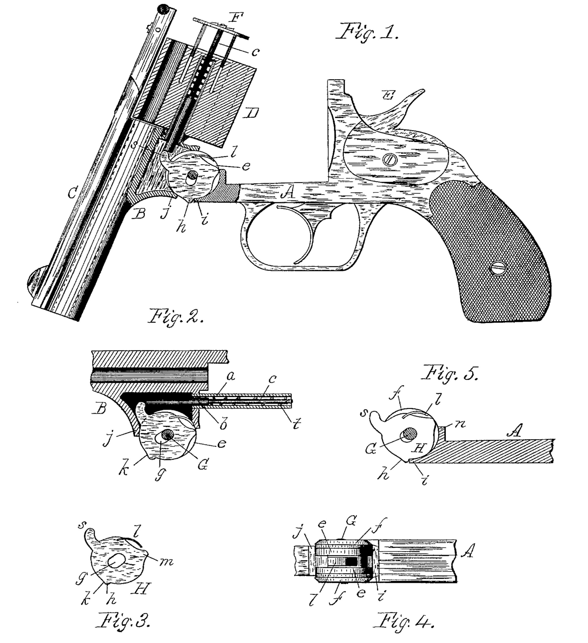
In Figure 1 is shown a sectional elevation of a weapon embodying my improvements with the extractor in an active position. Fig. 2 shows a portion of the barrel-frame with the extractor-lifter in its normal position, or when the weapon is locked, while Fig. 3 is a plan of the extractor-lifter, and Fig. 4 a plan of a part of the weapon, showing the position of the lifter within the joint thereof when the weapon is open, while Fig. 5 is a section of a portion of the frame A and ear f, showing the relative position of the extractor-lifter thereto when the latter is held fixed to actuate the extractor.
In the above drawings, A represents the frame or stock portion of the fire-arm, while B is the frame upon which is formed the barrel C. The revolving cylinder is shown at D and the hammer at E. The cylinder D, carrying the cartridges, is revolved and actuated in the usual manner, and is mounted upon a tubular rod, a, secured to the barrel-frame B.
The extractor is represented at F, and is provided with an actuating-pin, b, provided with a reduced portion, c, securely attached to the extractor F. Coiled about this portion c of the extractor-pin is a spiral spring, t, which is retained between the shoulder d and the rear face of the cylinder. Thus the tension of this spring is normally exerted against the cylinder to retain and hold the extractor closed or inactive. This actuating-pin b lies within the tubular rod a, and projects beyond and into a recess formed in the metal composing the frame B. The latter is pivotally attached and jointed to the frame A by means of two circular disks or ears, e e, which fit within and engage two oppositely-disposed but similar ears, f f, cast upon the stock part of the frame A. These parts are united by the pin G, and unitedly form the joint by which the ‘‘barrel” and ‘‘butt” of the fire-arm are connected together. Centrally of this joint, as shown in Fig. 4, and between the ears e e, is disposed the extractor-lifter H, which is mounted upon the pin G by means of the slot g, whereby lateral displacement of the lifter is made bodily during the act of locking or breaking the weapon. The extractor-lifter (a circular metallic disk or plate) is provided with a projecting arm or nose, s, which is normally in engagement with the extractor-pin b. (See Fig. 2.) Furthermore, this lifter is peripherally constructed with a cam-tooth, h. This tooth not only serves to render the lifter active by the engagement of one of its faces with the shoulder i on the frame A, but also serves to render said extractor-lifter inactive by movement of the shoulder j upon the opposite face of said cam-tooth. This engagement or travel of the shoulder j over the surface k of the cam-tooth h tends to thrust the entire lifter bodily or eccentrically on the pivot G when in the act of releasing the extractor-pin and extractor. Upon the periphery of said lifter, and nearly opposite the cam-tooth h, I have disposed a spring, l, within a depression formed by the projection m. The latter thus prevents the spring from catching upon the lip n on the frame A when in the act of locking or closing the weapon. The function and object of this spring l is to return and thrust back to its normal position the lifter H after the nose s has been disengaged from the extractor-pin b.
The operation of my automatic extractor-lifter is as follows, presuming the weapon is now in the act of being broken for the purpose of reloading: For convenience of illustration I will suppose the butt-end or stock portion of the arm is maintained in a fixed position and held in the right hand while the barrel C and frame B are revolved about the pin G as the center of rotation by means of the left hand. The action of the coiled spring t is to retain the extractor and its actuating-pin b against the nose s of the lifter; hence the parts contained in the barrel portion of the frame B remain at rest until the cam-tooth h is brought in contact with the lip i upon the frame A, owing to the movement of the barrel upon its pivots. When this occurs, the extractor-lifter H becomes fixed, as if it were a part of the frame A. Continued rotation of the barrel now causes the frame B to move about said lifter, while the extractor-pin and extractor F are gradually raised and advanced out of the cylinder, thereby ejecting from the latter the empty shells. When the extractor has about reached the limit of its active travel, the lip j has advanced, and is now impinging upon the surface k of the cam-tooth h. The result of this is that the lifter H is pushed transversely of the pin G, moving eccentrically of the latter by means of the slot g. The pin G now stands at the opposite end of said slot. The movement of the extractor-lifter H causes the disengagement of its cam-tooth h and the lip i upon the frame A, and the lifter is then free to rotate. This further continued movement of the lifter H is effected by means of the spring t, which now withdraws the extractor and at the same time actuates the lifter, since the latter is free to revolve about the pivot-pin G.
Fig. 1 represents the extractor in an active or fixed position, and just prior to its release to be effected by the approach of the lip j.
During the movement of the lifter eccentrically of the pivot it will be seen by Fig. 1 that the plate-spring l rests freely between the frames A B of the weapon; hence the displacement of said lifter upon the pivot G is easily accomplished. After release of the extractor-lifter H and actuation of the latter by return of the extractor to its inactive position, it is apparent that the spring l has been carried within the frame B, and is now in a state of compression. Thus, as the barrel C and frame B are reversed and swung back in a contrary direction or retreat movement, in order to close the weapon, the lifter is also oppositely rotated loosely about its pivot, and no active effect is produced upon the extractor, which remains at rest. The spring l now exerts its function and thrusts the lifter as the latter revolves transversely of the pivot G until centered upon the latter, as shown in Fig. 2. The cam-tooth h is now in its normal position in readiness to engage the lip i and drive the extractor outwardly in the act of breaking the weapon for reloading.
The mechanism above described is simple, automatic, and effective, since there is in reality but one essential part—viz., the extractor-lifter, and this forms a part of the joint of the weapon. The operation of this component part in effecting the movement of the extractor in the expulsion of the empty shells from the weapon is, first, advance movement centrally and loosely on its pivot; second, cessation of such movement and consequent outward travel of the extractor; third, release of said lifter by a relative change of the latter eccentrically of its pivot with further advance rotary movement thereof accompanied by retreat of the extractor; and, finally, contrary swinging motion freely upon its pivot and again transverse motion upon the pivot about which it is again centered.
I claim—
1. The combination, with the barrel and stock frames of a fire-arm and the cylinder containing a spring-actuated extractor, of the pivoted radially-slotted extractor-lifter and a spring acting thereon, but exterior thereto, substantially as set forth.
2. The extractor-lifter H, constructed with the radial slot g, the double faced cam projection h, peripherally-disposed spring l, and actuating-nose s, in combination with extractor F, its actuating-pin b, on which said nose operates, the barrel C, and stock-frame A, all operating substantially as herein described.
3. In combination with the frame portion A B of a fire-arm pivotally united at G and provided with the shoulders i j, the extractor, the slotted extractor-lifter H, also pivoted to said frame, its actuating-nose s, the double-faced cam projection h, and the spring l, exterior to said extractor-lifter, but acting thereon, the said extractor-lifter being alternately engaged by said shoulders i j, and operating as herein set forth.
4. In combination with the frame A and its shoulder i, the extractor-lifter pivoted thereto and provided with the cam h, nose s, and the extractor acted on by said nose, said cam being held fixed in engagement with said shoulder by the spring l, whereby the extractor is raised and the shells are ejected, substantially as described.
5. The combination, with the ejector, the frame A, its shoulder i, the extractor-lifter H, pivoted thereto and provided with the cam projection h, of the frame B and shoulder j, and the spring l, exterior to said extractor-lifter, but bearing thereon, the movement of shoulder j on the face k of cam h thrusting the lifter H bodily and eccentrically of its pivot to release the extractor, substantially as herein set forth.
In testimony whereof I affix my signature in presence of two witnesses.
GEO. H. FOX.
Witnesses:
H. E. LODGE,
E. K. BOYNTON.