
US 352185
UNITED STATES PATENT OFFICE.
HENRY GOODMAN, OF ST. LOUIS, MISSOURI, ASSIGNOR FOR DANIEL P. KANE,
OF SAME PLACE.
REVOLVER.
SPECIFICATION forming part of Letters Patent No. 352,185, dated November 9, 1886.
Application filed February 6, 1886. Serial No. 191,041. (No model.)
To all whom it may concern:
Be it known that I, HENRY GOODMAN, of the city of St. Louis, in the State of Missouri, have invented a certain new and useful Improvement in Revolvers, of which the following is a full, clear, and exact description, reference being had to the accompanying drawings, forming part of this specification, and in which–
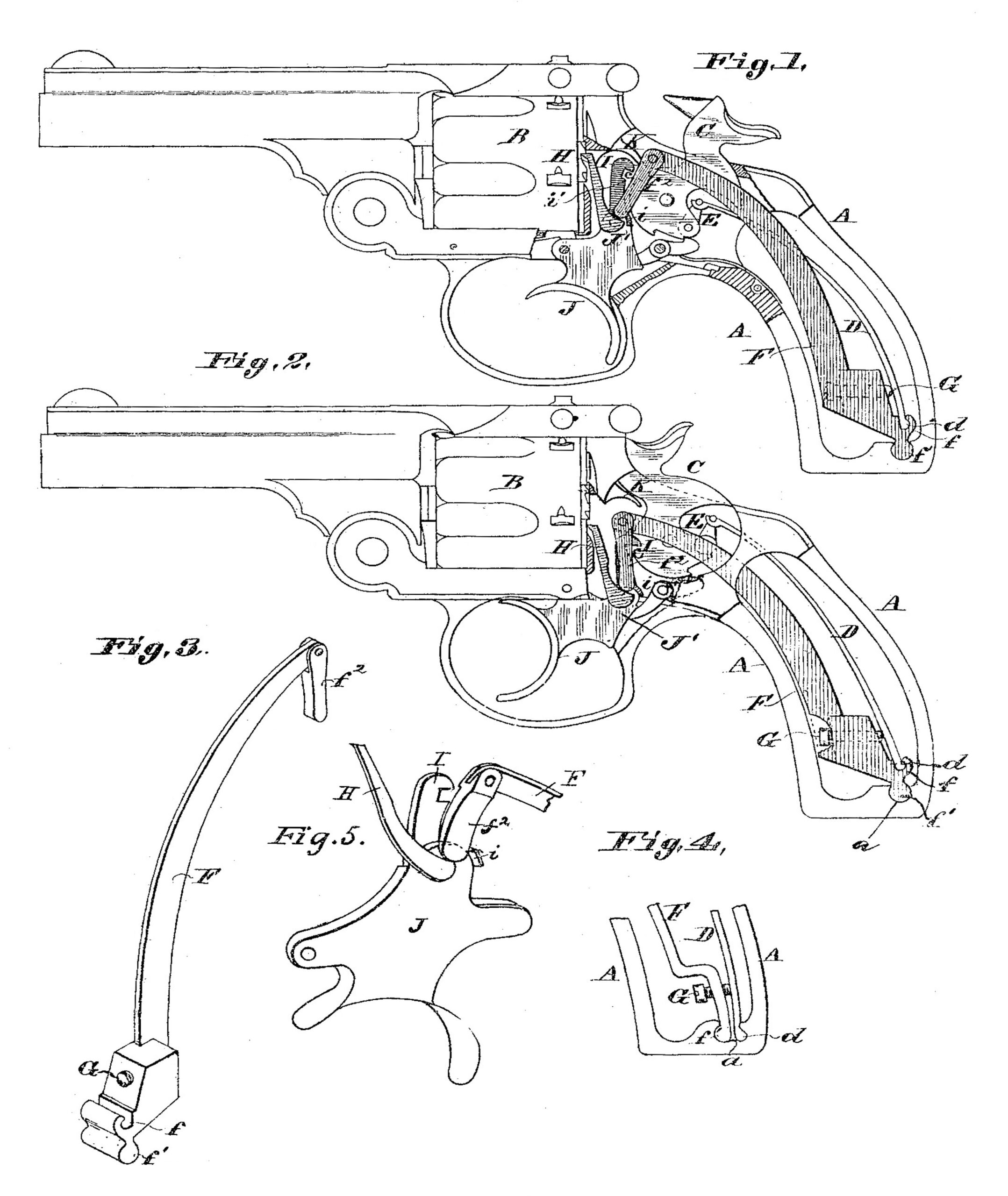
Figure 1 is a side view with parts removed, the hammer being at cock. Fig. 2 is a similar view, the hammer being down, Fig. 3 is a perspective view of the spring-lever. Fig. 4 is a detail side view showing a modification. Fig. 5 is a detail perspective view showing the relative positions of the trigger, the cylinder-pawl, the cocking-pawl, and the “push-piece” or finger for holding them in operative position.
This improvement is shown applied to a Smith & Wesson double-action revolver, but is applicable to other double-action revolvers; and it consists in connecting the mainspring with a lever which has hinged to its free end a finger or push-piece that bears against the both the pawl by which the hammer is cocked on pulling the trigger and the pawl by which the cylinder is turned.
A is the stock-frame; B, the cylinder; C, the hammer, to which the free end of the mainspring D is connected by a stirrup, E, at its free end, as usual. The other end of the mainspring has a transverse bead or projection, d, which fits in a recess, f, in a lever, F, whose lower end is fulcrum in the frame A by means of the cylindrical bead f’, which works in a cylindrical recess, a, in the lower bar of the frame.
G is a set-screw threaded in the lever, and whose point bears against the spring D, to give means for increasing or diminishing the force of the spring, which at the same time increases or diminishes the force with which the free end of the lever F is pressed downward.
F2 is a finger or push-piece hinged to the upper end of the lever F, whose lower end bears at the front side upon the pawl H, by which the cylinder is turned in the usual way, and at the rear side against a projection, i, of the cocking-pawl I. The cocking-pawl is of the usual construction, except for the projection i. Thus it will be seen that the finger or push-piece f2 acts constantly to press the pawl H forward and the pawl I rearward by bearing downward between them, while at the same time the trigger J will be forced forward, as said pawls are both hinged to its rear extremity, J’.
In the modification shown in Fig. 4 the lower ends of the mainspring D and the spring-lever F are fulcrumed in the same recess a of the stock-frame.
The operation is as follows: Upon pulling back the trigger J, to whose rear part the cock-pawl I and cylinder-pawl H are hinged, the tooth i’ of the said cocking-pawl engages a projection, c, of the hammer and forces up the hammer until the upper end of the front gear comes in contact with the incline K. As the end of the cocking-pawl slides along the incline it moves forward and the tooth is disengaged from the projection c, and the hammer being released is thrown forward by the mainspring. As the hammer is raised the pawl H turns the cylinder forward to bring another cartridge in line with the barrel K in the usual manner. On relieving the trigger the spring-lever F forces it to its forward position.
I am aware that a fire-arm has been provided with a set-screw, whereby to regulate the amount of power exerted by the mainspring; but this is not the equivalent of my invention, nor do I claim it.
I claim as my invention—
1. The combination, with the hammer, the trigger, and the cocking-pawl hinged to said trigger and adapted to engage said hammer, of the mainspring engaging said hammer, a lever acted upon by said mainspring, and a finger or push-pieced carried by said lever and bearing against said cocking-pawl for holding it normally in engagement, as set forth.
2. The combination, with the hammer, the trigger, and the cylinder-pawl hinged thereto, of the mainspring engaging said hammer, a lever upon which said mainspring acts, and a finger or push-piece carried by said lever and bearing against said cylinder-pawl for holding it in working position, as set forth.
3. The combination, with the hammer and the trigger, of a mainspring engaging said hammer, and a lever upon which said mainspring acts, having a finger or push-piece hinged to the free extremity of said lever and engaging at its free extremity with said trigger for holding it normally in forward position, substantially as set forth.
4. The combination, with the hammer and the trigger having the cocking-pawl and the cylinder-pawl pivoted thereto, of a mainspring engaging said hammer, and a lever acted upon by said mainspring, having a finger or push-piece engaging said pawls and forcing them in opposite directions, substantially as set forth.
5. In a fire-arm, the combination, with the hammer, a mainspring engaging therewith, and a lever, substantially as and for the purpose described, fulcrumed within the stock, of a set-screw tapped into said lever and bearing against said mainspring for regulating the force exerted upon said lever and the hammer.
6. The combination, with the hammer C and the mainspring D, engaging therewith, of the lever F, for the purpose set forth, fulcrumed within the stock and engaged near its fulcrum by said mainspring, as described.
HENRY GOODMAN.
In presence of—
SAML. KNIGHT,
BENJN. A. KNIGHT