
US 355233
UNITED STATES PATENT OFFICE.
DANIEL L. TOWER, OF BROOKLYN, NEW YORK.
EXTRACTOR FOR REVOLVERS.
SPECIFICATION forming part of Letters Patent No. 355,233, dated December 28, 1886.
Application filed July 15, 1886. Serial No. 208,091. (No model.)
To all whom it may concern:
Be it known that I, DANIEL L. TOWER, of Brooklyn, in the county of Kings and State of New York, have invented a new and useful Improvement in Extractors for Revolving Pistols; and I do hereby declare that the following is a full and exact description thereof, reference being had to the accompanying drawings, and to the letters of reference marked thereon, making a part of this specification, in which—
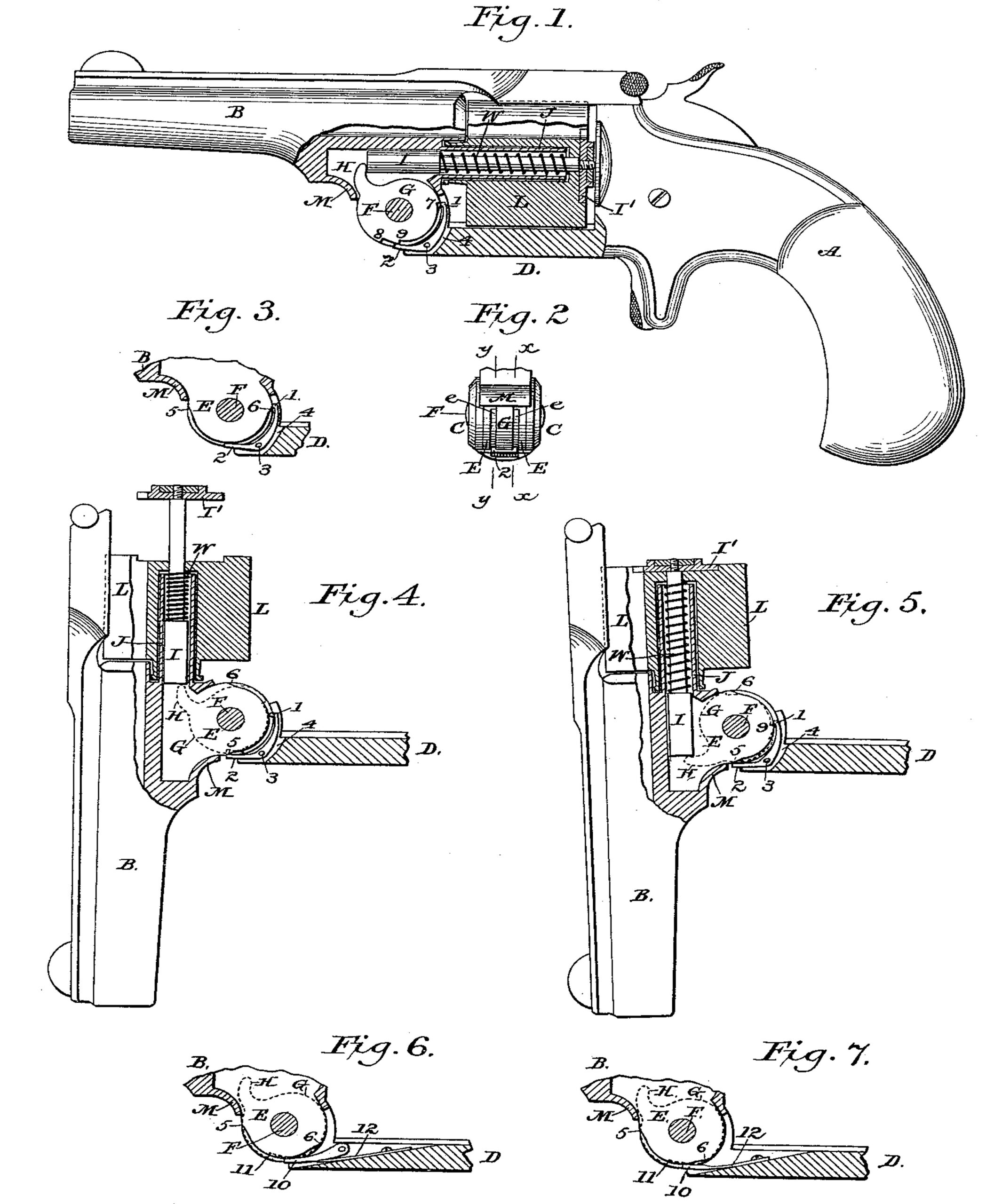
Figure 1 is a side elevation, partly in section, of a revolver fitted with my improved cartridge-extractor, the sectional portion being taken in line x x of Fig. 2, to illustrate the devices by which the extractor is automatically operated. Fig. 2 is a detached view of the joint between the barrel of the pistol and its handle. Fig. 3 is a detached sectional view in line y y of Fig. 2, illustrating the several parts in the same position as in Figs. 1 and 2. Fig. 4 is a detached view, partly in section, of the barrel and a portion of the handle of the pistol, illustrating the barrel as swung open on its joint far enough to produce the extreme outward movement of the extractor, (the section being in same line as in Fig. 1.) Fig. 5 is a view similar in all particulars to Fig. 4 excepting that the barrel has been swung open to its utmost extent, thereby effecting a release of the extractor, which is illustrated as having returned to its first position. Figs. 6 and 7 are detached sectional views similar to Figs. 3, but which illustrate modifications in
the device for operating the extractor.
Similar letters indicate like parts in all of the figures.
My invention relates to the devices by which the swinging open of the barrel of a revolving pistol jointed in the customary manner to its handle is made to force out a cartridge-extractor and to permit of an automatic return of the latter to its first position so soon as its extreme outward movement is completed.
It has for its object to simplify the mechanism by which the movement of the extractor is effected; and it consists in the construction and combination, as hereinafter set forth, of certain novel devices for this purpose.
A represents the handle, and B the barrel, of a revolving pistol of the type known as the ‘‘Smith & Wesson.” The barrel is articulated to the handle in the customary manner, C C, Fig. 2, representing the circular lugs or ears at the extremity of the bar D of the handle, between which the counterpart, circular lug, or joint-piece of the lower portion of the barrel is inserted, and F the transverse pivot-pin upon which the two parts mutually turn. The lug or joint-piece projecting from the barrel to form the central leaf of the hinged joint is centrally recessed parallel with its sides, so as to be divided in effect into two lugs or joint-pieces, E E, and in this central recess, between the lugs E E, a circular plate or disk, G, is fitted is turn freely upon the pivot-pin F. This loosely-revolving disk G is formed with a finger, H, projecting from its periphery far enough to engage the inner end of the extracting-rod I, which is fitted in the customary manner to extend through the tubular spindle J, upon which the cylinder of the pistol revolves. This, rod, of the usual form, is carried inward by a spiral spring, W, encircling it within its seat in the tubular spindle J, and is provided with a retracting-disk, I’, at its outer end, to engage the flanges of the cartridges inserted in the chamber of the cylinder L, all in manner as is common to pistols of this class.
Thus far the parts described need not differ essentially from similar parts as found in pistols of this description as ordinarily constructed.
My improvements consist in the employment of a catch plate or lever which may be bent and formed with two arms, 1 2, said catch-plate being fitted within a recess, 4, in the bar D of the handle, and therein pivoted upon a transverse pin, 3, so that its longer arm, 1, shall bear, as shown in Fig. 1, against the periphery of the loose disk G between the bar D and the barrel B, when closed; and its shorter arm, 2, shall bear against the periphery of the disk at a point just beyond or near to the extremity of the bar D. The ends of this catch-plate 1 2 are so much wider than the disk G, however, as to overlap and bear directly upon the periphery of the two lugs or joint-pieces E E, which embrace the disk. To permit, therefore, of an engagement of the arms 1 and 2 of the catch-plate with the periphery of the intermediate disk G, the periphery of each lateral lug E E is partially cut away to form a cam between the points 5 and 6, as shown in the drawings, and as represented at e e in Figs. 2 and 3. The periphery of the disk G, moreover, is also so cut away between the points 7 and 8 (see Fig. 1) as to leave shoulders 7 and 8 at each end of the intermediate peripheral recess, and a tooth, 9, near to the shoulder 8, as illustrated in Fig. 1. An engagement of the longer arm, 1, of the catch-plate with the tooth 9 is provided for by forming an inwardly-projecting lug or hook at the extremity of said arm.
The peripheral recess 7 8 on the disk G is so located with reference to the finger H as that when said finger is in contact with the inner end of the extractor I—the pistol being closed and the extractor in its inner position, as shown in Fig. 1—the end of the shorter arm, 2, shall be in close proximity to the shoulder or notch 8 on the disk, and the end 1 of the longer arm shall be immediately in front of or close to the shoulder 7 of the disk. The cam or peripheral recess on each of the lugs E E is so proportioned in length and so located with reference to the finger H on the disk G and to its position relatively to the catch-arms 1 2 as that when the disk and catch-plate are in the position last indicated, and which is illustrated in Fig. 1, (in which the disk is shown in positive lines,) the end 1 of the longer arm will rest upon the enlarged concentric periphery of the disk just beyond one end, 6, of the cam, so as to be held thereby out of engagement with the disk, while the end of the opposite shorter arm, 2, of the catch shall rest in the recess midway of its length, as illustrated in Fig. 3, (in which the lug E and its cam-recess 5 6 are shown in positive lines.)
When the pistol is closed and the extractor in its inward position, (see Fig. 1,) the outer edges of the end 1 of the catch-plate will rest upon the wider portion of the periphery of the lateral lugs E E, just beyond the cam e, in each, and will be thereby upheld out of engagement with the periphery of the central disk, G, carrying the arm H, against which the inner end of the extractor bears under the influence of its spring W. The outer edges of the opposite end, 2, of the catch-plate, when it is in said position, are over the central portion of the cam-recess e in the lateral lugs E E, and consequently this end 2 is left free to rest upon the periphery of the disk G, and it bears thereon just in advance of the shoulder 8 at the end of the recess 7 8 in ad periphery of said disk G, as shown in Fig. 1. If, now, the barrel of the pistol be swung open upon the pivot F, shown in Fig. 4, the disk G will be locked and kept stationary by the engagement of shoulder 8 with the end 2 of the catch-plate, while the lugs or joint-pieces E E will turn with the barrel, on each side thereof. The movement of the barrel as it turns upon the pivot F will cause the extractor bearing at its inner end against the finger H, which is held stationary by the engagement of the catch-plate at 2 with the disk at 8, to move out from the cylinder L, and this outward movement is continued until, in the rotation of the lugs E E, the enlarged diameter beyond the ends at 5 of the cams e e, is carried under the lateral overlapping edges of the end 2 of the catch-plate, so as to lift the catch-plate out of its engagement with the notch or shoulder 8 in the disk G, and thereby release the disk, which, being now left free to revolve, will permit the extractor I to fly inward under the influence of its spring, said spring having been compressed as the extractor moved outward. When the enlarged diameter of the lateral lugs E E reaches the end 2 of the catch-plate to produce its disengagement from the disk, the opposite end, 1, of the plate is over the cam-recesses e e of said lugs, and the required inward movement of said end 1, as the catch-plate works upon its pivot 3, is thereby permitted. The rotation of the disk G under the influence of the spring W, as the extractor I, bearing upon the finger H, moves inward, is arrested, when said movement is completed, by the engagement of the hook at the end 1 of the catch-plate with the tooth or notch 9 (see dotted lines, Fig. 5) on the disk. This partial revolution of the disk G will bring the finger H in position to be engaged by the inner end, M, of the barrel, as illustrated in Fig. 5, so that as the barrel is swung back upon its pivot F it will carry with it the finger H and the disk G to the first position thereof, as shown in Fig. 1.
As a modification of the invention, a simple pivoted catch-lever, 10, (see Fig. 6,) may be substituted as an equivalent for the double-ended catch-plate 1 2, the end of the lever being brought into play to engage a notch, 1 1, in the disk G by means of a spring, 12. The lever is released from the notch 11, when the extractor has been forced outward to its extreme position, by means of the cams on the lugs E E, bearing, as hereinbefore described, upon the overlapping edges of the catch-lever, so as to operate as the lugs revolve to lift the catch out of the notch. In this case the rotation of the disk G is arrested by the inner end, M, of the barrel. So soon as the barrel is closed the catch is permitted to drop inward into engagement with the disk G by a cam-recess, 5 6, in the periphery of the lugs or joint-pieces E E, as has been hereinbefore described. It is evident that a cam upon one only of the lugs or gone pieces may be employed, instead of the two.
As a further modification the catch-lever 10 be made integral with the spring 12, as illustrated in Fig. 7, instead of being detached therefrom and pivoted, as shown in Fig. 6.
I claim as my invention—
1. The combination, with the spring-actuated extracting-rod in a revolver, of a circular lug or joint-piece projecting from the barrel and constituting one part of the knuckle-joint connecting the barrel with the handle of the revolver, a cam upon the periphery of said lug, a disk of a diameter corresponding with that of said lug revolving loosely upon the joint-pin and having a notch and recess in its periphery, a catch plate or lever pivoted to the handle to overlap and engage the peripheries of the disk and adjacent lug, and a finger projecting from the disk to engage the inner end of the extractor, all substantially in the manner and for the purpose herein set forth.
2. The combination, in a pistol, of the handle A, barrel B, spring-seated extractor I, knuckle-joint C E between the handle and barrel, disk G, revolving loosely upon the joint-pin, finger H, projecting from said disk to engage the extractor I , projection M from the barrel to engage said finger H, and a catch-plate or lever pivoted to the handle to overlap and bear upon the adjacent peripheries of the disk G and joint-piece E, said disk and joint-piece being severally recessed to permit of an engagement of the lever with the disk when the barrel is closed, maintain it until the barrel is nearly opened, and finally break it when fully opened, all substantially in the manner and re the purpose herein set forth.
In testimony whereof I have signed my name to this specification in the presence of two subscribing witnesses.
DANIEL L. TOWER.
Witnesses:
A. N. JESBERA,
S. A. STAVERS.