
US 355761
UNITED STATES PATENT OFFICE.
SULLIVAN FOREHAND, OF WORCESTER, MASSACHUSETTS.
REVOLVER.
SPECIFICATION forming part of Letters Patent No. 355,761, dated January 11, 1887.
Application filed October 25, 1886. Serial No, 217,087. (No model.)
To all whom it may concern:
Be it known that I, SULLIVAN FOREHAND, a citizen of the United States, residing at Worcester, in the county of Worcester and State of Massachusetts, have invented a new and useful Improvement in Revolving Fire-Arms; and I do hereby declare that the following is a full, clear, and exact description thereof, which, in connection with the drawings making a part of this specification, will enable others skilled in the art to which my invention belongs to make and use the same.
My invention relates to that class of revolving fire-arms in which a many-chambered revolving cylinder is used in connection with a single barrel; and it consists in the novel manner of connecting the cylinder with its central stem or spindle, upon which it revolves, as will be hereinafter fully described.
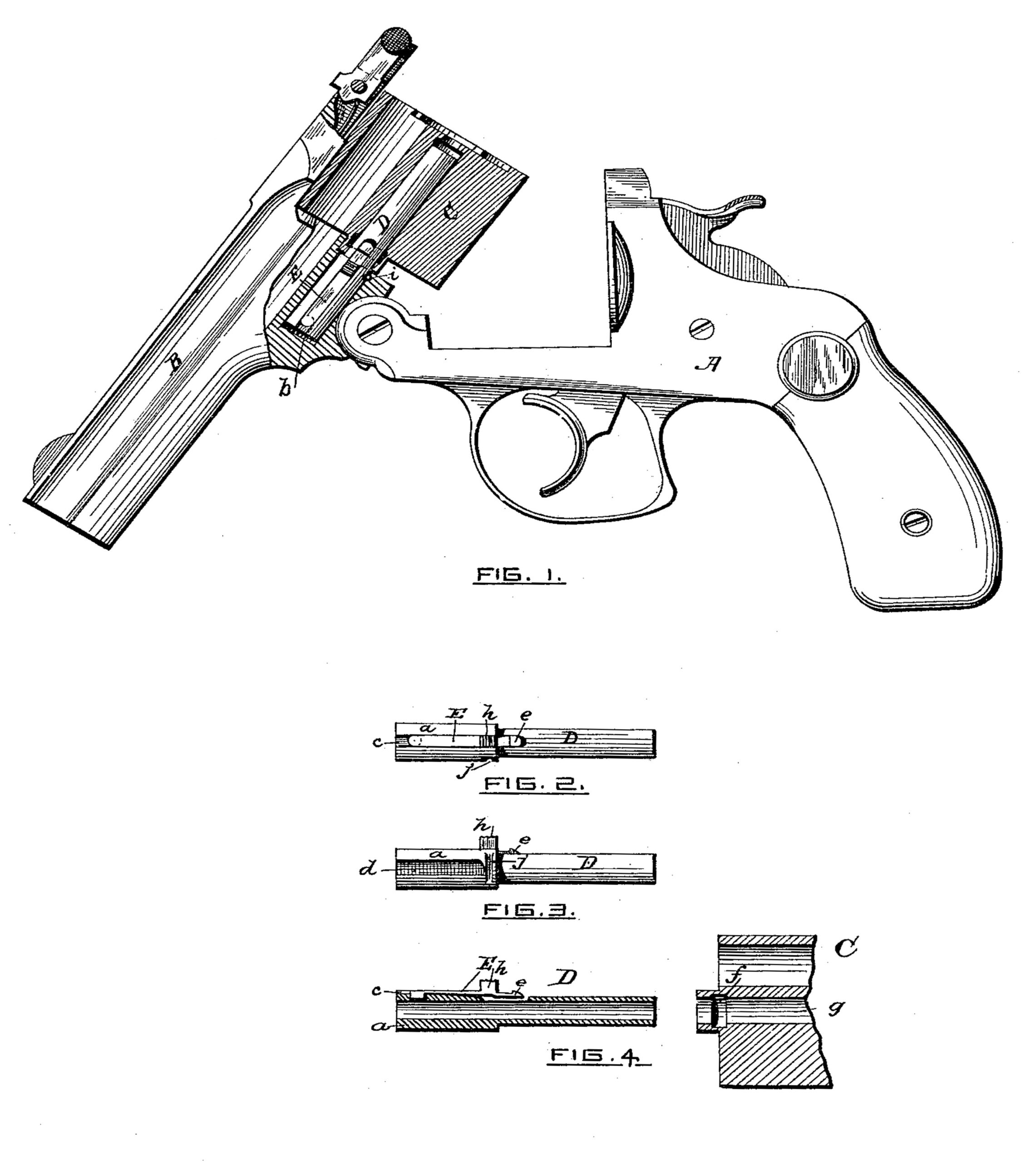
Referring to the drawings, Figure 1 represents a side elevation of a revolving fire-arm with parts broken away to more clearly illustrate my invention applied thereto. The barrel portion is shown tilted upon the stock. Fig. 2 represents a plan view of the central spindle of the cylinder detached from the revolver; Fig. 3, a side view of the spindle; and Fig. 4, a central vertical section of the spindle, and also of a portion of the cylinder.
In the drawings, A is the stock of a revolver of any ordinary construction. B is the barrel portion; hinged to the stock and adapted to be tilted thereon, as shown.
C is the cylinder, supported upon and secured to the central stem or spindle, D, and adapted to revolve thereon. The spindle D is made hollow, as shown, adapted to receive the ejector-stem, upon the end of which is secured the cartridge-ejector in the usual manner, the ejector being operated by means of an ejector-lifter secured at the hinge of ‘the revolver in any usual and well-known manner.
I have not shown in the drawings the ejector and means for operating the same, as they form no part of my present invention, and are old and well-known devices usually employed in this class of revolving fire-arms.
The spindle D may be enlarged at one end, and said enlarged end a be adapted to fit tightly into a hole, b, formed in the barrel portion B of the revolver. (See Fig.1.) A longitudinal groove, c, is made in the exterior surface of the end a of the spindle D, which at its inner end may extend through the shell of the spindle, as shown in Fig. 3. A longitudinal opening or slot, d, may also be made in the end a, (see Fig. 2,) to allow of the lifter-finger moving back and forth therein to operate the ejector-stem and ejector in the usual manner.
A flat spring, E, is fitted into the groove c, and secured therein in any suitable manner, so that its upper surface will be flush with the exterior surface of the end a of the spindle D. (See Figs. 2 and 3.)
The forward end of the spring E projects beyond the portion a of the spindle D, and has a hook or catch, e, formed thereon, adapted to engage with a circular recess, f, formed in the central part, g, in the forward end of the cylinder, (see Fig. 4,) when the cylinder is in its proper position upon the spindle D.
A knob or projection, h, is formed upon the upper side of the spring E, and extends up from the same and through an opening in the barrel portion made to receive it, and its upper end projects above the plane surface of the barrel portion. By means of the knob h the catch e is depressed, allowing the cylinder
C to be disconnected and removed from the spindle D. The knob h, projecting through an opening in the barrel portion, also prevents any rotation of the spindle D.
I prefer to have the end a of the spindle D fit so tightly in the hole b, formed in the barrel portion, that it cannot be readily drawn out; but it may be made to fit somewhat loosely therein, and be prevented from being drawn out by a small pin, i, secured in the barrel portion and fitting into the vertical groove j, made in the outer surface of the enlarged end a of the spindle D. (See Figs. 2 and 3.)
From the manner of construction of the spindle or stem D above described, in connection with the circular recess f, formed in the central opening of the cylinder C, it will be readily seen that the cylinder C will be securely held in position and prevented from any longitudinal motion upon its central supporting
spindle or stem, D, and at the same time be allowed to revolve freely thereon, and to be disconnected and removed therefrom, when desired, by simply pressing upon the knob h, which projects out above the plane surface of the barrel portion B, as before stated.
I have shown in the drawings the circular recess f formed upon the internal surface of the central part, g, of the cylinder C, adapted to be engaged by the notched end of the spring E from the interior; but it will be understood by those skilled in the art that the circular recess f may, if preferred, be formed in the exterior surface of the central part of the cylinder, which projects beyond the end of the cylinder, (see Fig. 4,) and the spring E be made so that its notched end will extend through the barrel portion B, at either side of the spindle D, and engage the external recess formed on the central part of the cylinder, upon the opposite side from which the knob A extends, without departing from the principle of my invention, which covers, broadly, a tubular central stem or spindle provided with a spring adapted to engage with the cylinder to secure the same to the stem, and at the same time allow of the free rotation of the cylinder thereon.
Having thus described my invention, what I claim as new, and desire to secure by Letters Patent, is—
1. In a revolving fire-arm, the combination, with the revolving cylinder provided with a
circular recess for the purpose stated, of its hollow supporting-spindle provided with a spring having its end notched and adapted to engage with the recess above mentioned, to allow of the cylinder revolving freely upon said spindle and prevent any longitudinal motion thereon, substantially as set forth.
2. The combination, with the revolving cylinder C, provided with the circular recess f,
for the purpose stated, of the hollow stationary spindle D, and spring E, secured therein and provided with a catch adapted to engage with said recess f, substantially as and for the purpose stated.
3. The combination, with the tubular spindle D and spring E, provided with a knob, A, and catch e, of the cylinder C, provided with a circular recess, f, for the purpose stated, substantially as shown and described.
4. The combination, with the spindle D, having the groove c formed therein, and the spring E, provided with a knob, A, and a catch, e, secured in said groove, of the cylinder C, having a circular recess, for the purpose stated, substantially as shown and described.
5. The combination, with the barrel portion and the cylinder provided with a circular recess, for the purpose stated, of the spindle D, provided with a spring, E, and a pin, i, adapted to engage said spindle and prevent any movement thereof, all constructed substantially as set forth.
SULLIVAN FOREHAND.
Witnesses:
JOHN C. DEWEY,
M. RALPH DRYDEN.