
US 357710
UNITED STATES PATENT OFFICE.
JOHN C. HOWE, OF WORCESTER, MASSACHUSETTS.
REVOLVING FIRE-ARM.
SPECIFICATION forming part of Letters Patent No. 357,710, dated February 15, 1887.
Application filed November 13, 1886. Serial No. 218,759. (No model.)
To all whom it may concern:
Be it known that I, JOHN C. HOWE, a citizen of the United Slates, residing at Worcester, in the county of Worcester and State of Massachusetts, have invented a new and useful Improvement in Revolving Fire-Arms; and I do hereby declare that the following is a full, clear, and exact description thereof, which, in connection with the drawings making a part of this specification, will enable others skilled in the art to which my invention belongs to make and use the same.
My invention relates to that class of revolving fire-arms in which a rotating or revolving cylinder is used; and my Invention consists in the novel manner of connecting the cylinder with the barrel portion, so as to allow of the cylinder revolving freely upon its central supporting-stem and prevent any longitudinal movement, except at the proper time, in the manner to be hereinafter fully described.
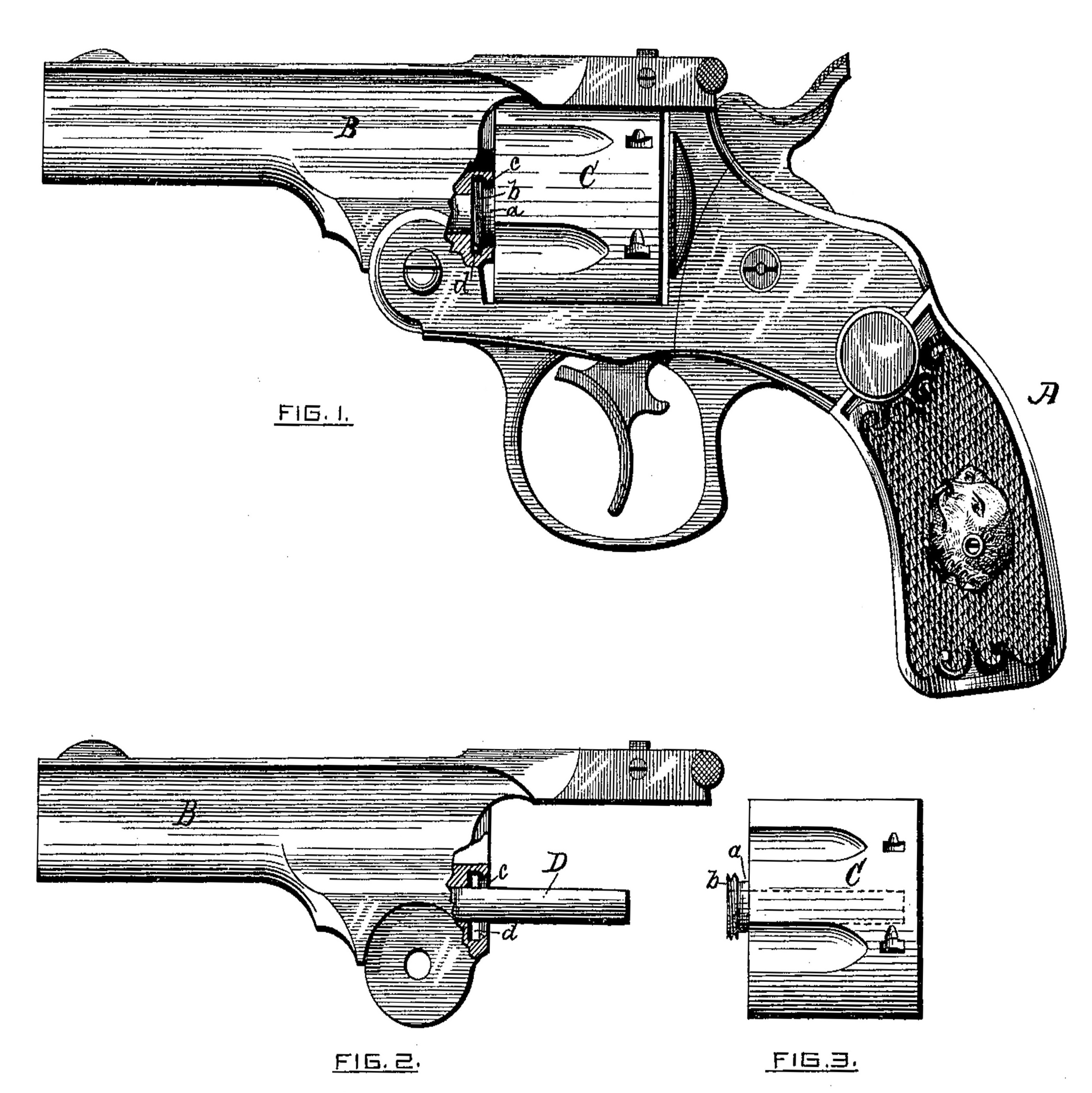
Referring to the drawings, Figure 1 represents a side elevation of a revolving fire-arm,
with parts broken away to more clearly illustrate my invention applied thereto. Fig. 2 represents a side elevation of the barrel portion detached, the cylinder-stem being shown, and a part broken away around said stem to illustrate one feature of my invention; and Fig. 3 is a side elevation of the revolving cylinder detached, showing the manner of construction of the same to carry out my invention.
In the drawings, the part marked A is the stock of a revolver of any ordinary construction.
B is the barrel portion, hinged to the stock and adapted to be tilted thereon in the usual
and well-known manner.
C is the revolving cylinder, having a central hole extending through it in the usual manner, adapted to receive the supporting stem D, upon which said cylinder revolves. The central tubular part, a, extending out from the cylinder C, has an enlarged screw-threaded end, b, adapted to engage with and screw through a screw-threaded socket, c, made in the barrel portion B around the stem D. (See Fig. 2.) An enlarged circular chamber or recess, d, is also made in the barrel portion B at the forward end of the screw-threaded socket c, in which fits loosely the enlarged end b of the tubular part a of the cylinder C, after said end b has been screwed through the socket c. Said enlarged recess d and the screw-threaded socket c (adapted to engage the screw-threaded end of the tubular part b of the cylinder C, as before described) are entirely independent of the central stem, D, said stem being of plain cylindrical shape throughout its length, and secured in the barrel portion B by driving it into a hole made therein, or in any other ordinary manner.
The cylinder C is connected with the barrel portion B by placing said cylinder upon the stem D and engaging the screw-threaded end b of the tubular part a with the screw-threaded socket c, made in the barrel portion B, and turning the cylinder until the end b passes entirely through the socket c and enters into the enlarged recess d beyond said socket c, in which recess said end b fits loosely.
After the cylinder C is connected with the barrel portion B, in the manner above described, and as fully shown in Fig. 1 of the drawings, said cylinder is free to revolve in either direction upon its central supporting-stem, D, the screw-threaded end b of the tubular part a revolving around in the enlarged recess d and preventing any longitudinal motion of the cylinder.
In order to remove the cylinder, it is only necessary to draw it away from the barrel portion and turn said cylinder so that the screw threaded end b of the tubular part a’ will engage with the screw-threaded socket c and will be turned out of the enlarged recess d.
It will be understood that my present invention relates only to the manner of connecting the revolving cylinder with the barrel portion of a revolver, so that it can revolve freely in either direction, but be prevented from moving longitudinally, except at the proper time; and said invention may be used in connection with revolving fire-arms of any well-known construction now in general use.
Having thus described my invention, what I claim as new, and desire to secure by Letters Patent, is—
1. The combination, with the barrel portion of a revolving fire-arm provided with a screw-threaded socket for the purpose stated, and having an enlarged recess at the forward end of said socket, of the cylinder having its central projecting tubular part provided with an enlarged screw-threaded end adapted to screw through the said socket in the barrel portion and fit loosely in the enlarged recess beyond, substantially as set forth.
2. The combination, with the barrel portion of a revolver provided with a screw-threaded socket, c, and having an enlarged recess, d, at the forward end of said socket, and the stem D, supporting the cylinder, which revolves thereon, of the cylinder having the projecting tubular part a, provided with an enlarged screw-threaded end, b, adapted to screw through the socket c in the barrel portion and fit loosely in the enlarged recess d therein, substantially as set forth.
JOHN C. HOWE.
Witnesses:
JOHN C. DEWEY,
M. RALPH DRYDEN.