
US 7493
UNITED STATES PATENT OFFICE.
GEO. LEONARD, JR., OF SHREWSBURY, MASSACHUSSETTS.
IMPROVEMENT IN REVOLVING-HAMMER FIRE-ARMS.
Specification forming part of Letters Patent No. 7,493. dated July 9, 1850.
To all whom it may concern:
Be it known that I, the undersigned, George Leonard, Jr., of Shrewsbury, in the county of Worcester and Commonwealth of Massachusetts, have invented new and useful improvements in Fire-Arms Embraced in a Pistol, of which the following is a full and exact description, reference being had to the accompanying drawings, forming part of this specification.
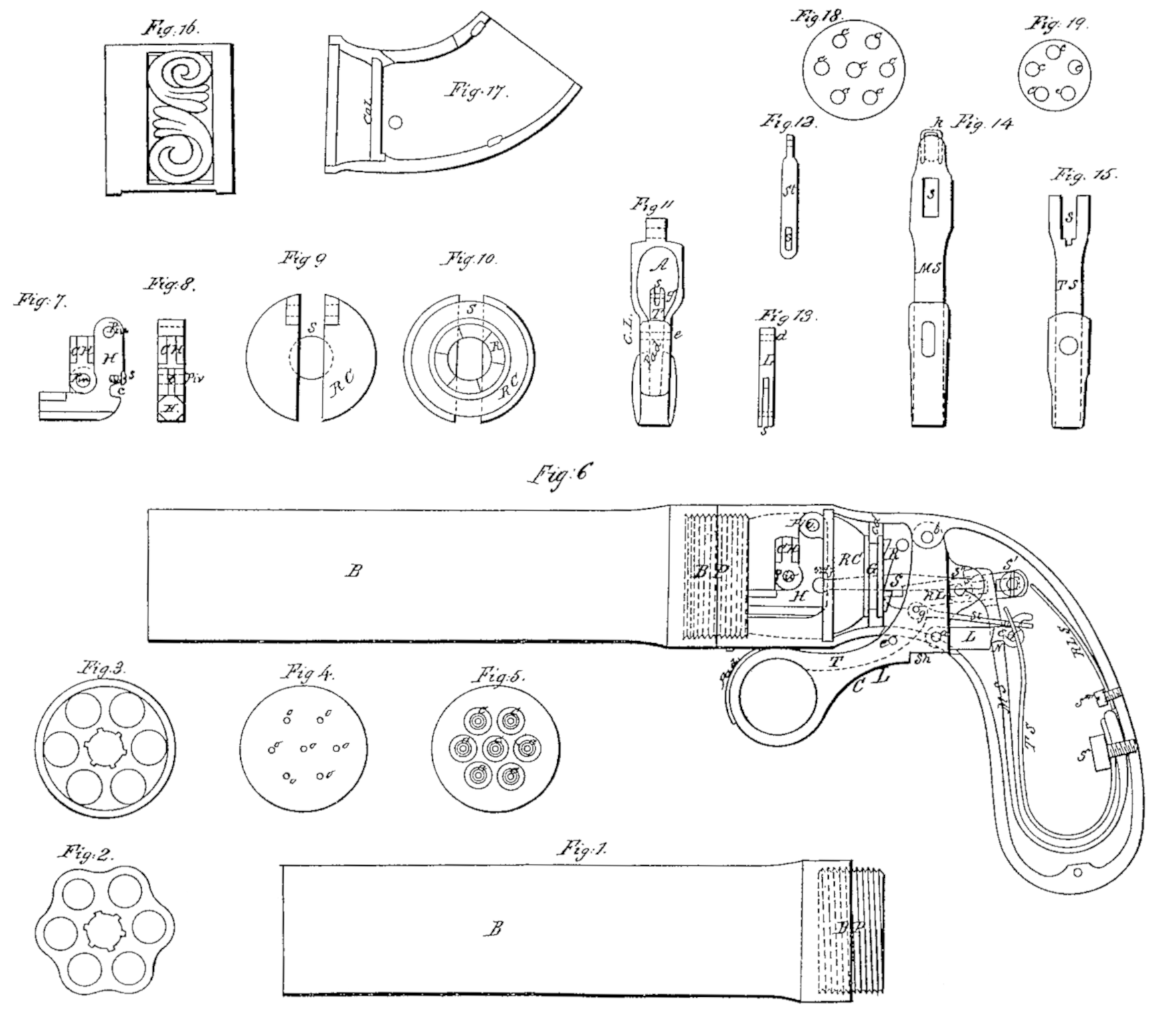
It has seven barrels, (marked Bin Figures 1 and 6.) a front view of which is exhibited in Fig. 2 and a back view in Fig 3. The barrels have a form somewhat similar to those in a common revolving pistol. They are drilled and bored entirely through. This is never done in revolving-pistols. They have a breech-pin which closes the whole seven barrels, and which fits an interior screw and cavity in the barrels exactly.
The breech-pin is marked B P in Figs. 1. and 6. Fig. 4 represents the front view, and o o o o o o o the orifices of the cones. Fig. 5 represents the back view, and c c c c c c c the cones. It seems almost impossible to close all of the seven barrels with one breech-pin, as is here done, so as to prevent all chance of communication from one barrel to another; but it has proved practicable and easy. One-half of the breech-pin projects out of the barrels, as shown in Fig. 1. The front part of the stock has an interior screw, which is screwed onto the projecting part of the breech-pin, as represented in Fig. G, and thus connects the stock with – the barrels.
The hammer H, Figs. 6, 7, and 8, revolves on a pin (marked, p i n, Figs. G and 7.) and strikes in regular succession, as the pistol is operated, the caps on the six exterior cones. The cap on the seventh or middle cone is exploded at any time by turning down with the finger the central hammer, C. H, Figs. 6, 7, and 8. This turning or revolution of the central hammer takes place on a pin (marked p i n, Figs. 6, 7, and 8.) passing through a tenon, t, Fig. 8, to which the central hammer is fitted by a mortise, and which is a portion of the hammer H, Figs. 6, 7, and 8. The central hammer, when turned down, projects some”what beyond the hammer, so as to render it impossible, to explode a cap on an exterior cone when firing one on the middle cone. The hammer has a cavity, c, Fig. 7., for one head of the sweep s, Fig,6, and the head is confined loosely in the cavity by the screw s, Fig. 7.
The revolving carriage R. C, Figs. 6, 9, and 10, is placed in the interior of the stock, about three-fourths of an inch back of the cones and breech-pin. It turns on a bearing (marked b e a r, Fig. 6.) which exactly fits the interior of the stock, and also in a groove, G, Fig. 6, which fits on a collar within the stock and cap of the stock c o l, Figs. 6 and 17, so as to retain the revolving carriage in its position and only allow it to turn. The hammer is attached to the revolving carriage by a pin, (marked pin, Fig.6,) and turns with the revolving carriage. The revolving carriage is turned by means of a ratchet, R, Figs. 6 and 10; which is operated upon by the ratchet-lever R. L, Fig. 6, and caused to revolve one-sixth at every stroke of the hammer.
The ratchet-lever is attached to the stock by a screw, s’, and to the cocking-lever C L, Fig. 6, by another screw, s”, turned upward. It has two slots, as shown, beneath s’ and s”, for these screws to pass through, and to allow longitudinal motion to enable it to slip over and fit the notches in the ratchet. It is operated by the cocking-lever by means of the screw s”. The ratchet-lever is kept firmly against the ratchet in all positions by the ratchet-lever spring R L S, Fig.6, which is attached to the stock by the screw s””, and bears against the back end of the ratchet-lever.
The mainspring M. S., Figs. 6 and 14, is attached to the stock by the screw s”’. A cavity is drilled into the other extremity or head, about one-fourth of an inch, into which one head of the sweep s, Fig.6,is inserted and confined loosely by the key k, Fig. 14, which is a crooked wire passing down each side of the neck of the sweep through holes in the head of the mainspring. The mainspring has a slot, s, Fig. 14, through which the latch L, Figs. 6 and 13, and stirrup, Figs. G and 12, pass.
The sweep is a cylindrical piece with two globular heads loosely confined, as above described, in the back of the hammer and head of the main spring. The blow is communicated from the mainspring to the hammer by means of the sweep.
The cocking-lever CL, Figs, 6 and 11, lies near the center of the stock. One end enters a slot in the stock. It is fastened to the stock by the pin b, Fig. 6. It passes through an aperture on the under side of the stock and terminates in a circular ring for the finger to pull by. It has a large slot, A, Fig. 11, for the sweep to pass through, and a groove in the upper part of the lower portion, in which the trigger T, Figs. 6 and 11, lies and exactly fits. A shoulder on the under side, s h, brings up against the stock and hinders the cocking-lever from being drawn farther back than is necessary.
– The trigger T., Figs. 6 and 11, lies in and fits the groove in the cocking-lever, as above stated. It plays on a pivot, e, and has a slot, s, Fig. 11, in its upper extremity, in which is fastened by the pivot g, Fig. 11, and plays, the stirrup s t, Figs. 6 and 12. It has a pad to protect and sustain the finger marked p a d, Figs. 6 and 11.
The stirrup s t is fastened, as above stated, to the trigger, and has a slot, s, Fig. 12, near its lower end, through which passes the top of the cam C, Fig. 6.
The latch L, Figs. 6 and 13, enters into a continuation of the groove already mentioned in speaking of the cocking-lever. It is fastened there, so as to play within, by the pin d, Figs. 6 and 13. It has a slot, s, Fig. 13, in the back end, in which is fastened by the pin f, i Fig.6, and plays, the cam C. It passes through the slot in the mainspring, and latches onto it by the notch N., Fig. 6.
The cam C has the position above stated. The front part of it rests on the bottom of the slot in the mainspring.
The trigger-spring T. S., Figs. 6 and 15, is fastened to the stock by the same screw, s”’, that attaches the… mainspring to the stock. The upper end has a slot, s, Fig. 15. This slot fits over the end of the latch and cam, Fig. 6, so that the spring presses against the pin f, which is sufficiently long for this purpose.
A sliding band, a side view of which is seen in Fig. 16, covers the cavity occupied by the hammer and protects the hand from fragments of exploding caps.
The pistol is operated as follows: be cocking-lever is pulled back by the middle finger, the notch in the latch drives the mainspring back, which carries back the sweep, and of consequence the hammer. The screw s”’, Fig. 6, raises the ratchet-lever, which carries the revolving carriage and hammer one-sixth round. Meanwhile the trigger-spring is raised and the ratchet-lever spring keeps the ratchet-lever firmly against the ratchet, and the end of the trigger rises and projects forward somewhat out of the groove in the cocking-lever. To discharge the pistol, while the middle finger still presses back the cocking-lever pull back the trigger by the forefinger. This draws forward the stirrup, which pulls over the cam so that the front part of the cam presses on the lower end of the slot in the mainspring, lifts up the latch, and allows the mainspring to drive forward the sweep and hammer. The middle finger is now slackened, when the trigger-spring drives forward the latch and cocking-lever, and forces down the latch so that the notch in it will again lock onto the mainspring. When the cocking-lever is moving forward the screw s” carries down the ratchet-lever, and the ratchet-lever spring then forces it forward into the next notch of the ratchet.
What I claim as my invention, and desire to secure by Letters Patent, is as follows:
1. A central hammer to be shifted from some convenient position so as to bear on the central cone and to be driven by the usual operations of the lock.
2. A revolving carriage to carry and turn the hammer.
3. A trigger turning on a pivot in the cocking-lever, and which is thrown forward into a position convenient to be drawn by pulling said cocking-lever. The whole to be substantially as herein described.
In testimony whereof I, the said George Leonard, Jr., hereto subscribe my name, in the presence of the witnesses whose names are hereto subscribed, on the 12th day of March, A.D. 1850.
GEORGE LEONARD, JR.
In presence of—
Elizabeth Davis,
Sylvester Davis.