
US 602870
UNITED STATES PATENT OFFICE.
GEORGE A. OWEN, OF SPRINGFIELD, MASSACHUSETTS.
REVOLVER.
SPECIFICATION forming part of Letters Patent No. 602,870, dated April 26, 1898.
Application filed August 2, 1897. Serial No. 646,777. (No model.)
To all whom it may concern:
Be it known that I, GEORGE A. OWEN, a citizen of the United States of America, residing at Springfield, in the county of Hampden and State of Massachusetts, have invented new and useful Improvements in Revolvers, of which the following is a specification.
This invention relates to revolving firearms, and more particularly to revolver-pistols in which the cylinder thereof is supported on a swinging yoke-frame which has its support in the main frame of the arm and whereby said cylinder is adapted to be swung out or to one side of the last-named frame and so far laterally or to one side thereof as to permit of ejecting cartridge-shells from said cylinder and of conveniently reloading the cylinder, the object being to provide in revolvers of the foregoing description automatically-operating means or mechanism actuated by the said swinging-out movement of the cylinder whereby simultaneously with said cylinder movement the shell-ejecting-devices of the arm are operated and are then caused to assume their normal positions relative to the cylinder, so that the latter may be again loaded; and the invention consists in the construction and arrangement of the parts of said mechanism and their adaptation for action upon said shell-ejecting devices, all as hereinafter fully set forth, and more particularly referred to in the claims.
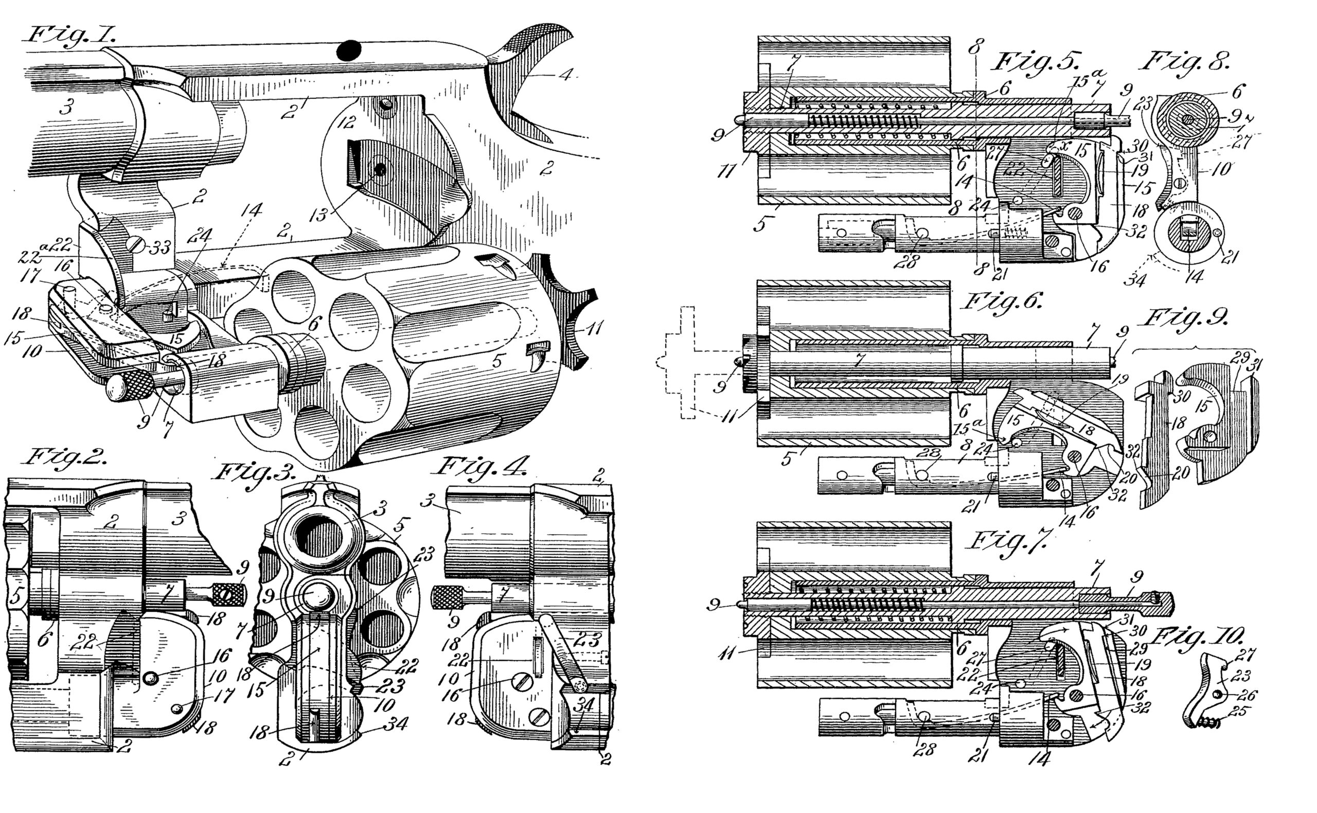
In the drawings forming part of this specification, Figure 1 is a greatly-enlarged perspective view of a revolving firearm (excepting the forward part of the barrel and the handle or stock thereof) having my improvements applied thereto, this figure illustrating the positions of the shell-ejecting mechanism immediately following the ejecting action thereof. Figs. 2 to 7, inclusive, illustrate in much enlarged views parts of the arm containing my said improvements and are hereinafter described. Fig. 8 is a sectional view on line 8 8, Fig. 5. Figs. 9 and 10 illustrate detail parts below described.
In the drawings the ordinary parts of the revolver to which my improvements are applied are designated as follows:
The frame is indicated by 2, the barrel by 3, the hammer by 4, the cylinder by 5. The cylinder-yoke 10 comprises the shaft 8, which has its bearing in the lower part of the frame 2 and the tubular cylinder-carrying arm 6. The ejector-piston operating in said tubular arm 6 is indicated by 7. The cylinder-locking pin 9 has the usual endwise movement, and one end engages in a socket 13, Fig. 1, in the recoil-plate 12, thereby retaining the cylinder in firing position within said frame 2. The shell-ejecting spider carried on the end of said ejector-piston 7 is indicated by 11. A spring-actuated pin 21 (see Figs. 5 to 7, inclusive) in the cylinder-yoke 10 has a bearing against a part of the frame 2 and serves to steady the swinging movement of said yoke. The said automatically-operating mechanism which actuates the shell-ejecting devices of the arm, as aforesaid, comprises the following elements and is constructed and applied to the arm and operates as below described. On said bearing-shaft 8 of the cylinder-yoke 10 in a suitable recess therein a spring 14 is firmly secured by one end by means of a pin 28, the latter entering said shaft transversely. An ejector-lever 15 is pivoted on a pin 16 in said cylinder-yoke 10, and has a short arm thereon on which the free end of said spring 14 bears, as shown, thereby tending to swing said ejector-lever 15 from the position shown in Fig. 5 to that shown in Fig. 6. Said ejector-lever 15 is constructed, as shown in Fig. 9 and elsewhere, with a slot 29 in its side and otherwise of the form shown, for purposes described farther on. A sliding ejector-pawl 18 has an operative position in said ejector-lever 15, as shown, and has a shoulder 30 thereon for engagement with a part 31 of said ejector-lever 15 when the latter is in the position illustrated in Fig. 5, where the upper extremity of said ejector-pawl 18 is shown in engagement with the end of said ejector-piston 7. A recess is formed in one edge of said ejector pawl 18, as shown, in which is placed a bow- shaped flat spring 19, which acts to impart more or less frictional resistance to the endwise movement of said pawl in said slot in which it operates. In one edge of said ejector pawl 18, near its lower end, is formed a cam and a pin-socket, which are indicated by 20. A pin 17 is fixed in one of the side plates of said cylinder-yoke and has its inner end held in the position relative to the inner end of said ejector-pawl, as shown in Figs. 5, 6, and 7, against which said cam 20 acts and with which said socket engages, as shown in Fig. 5. A slight projection 32 on said ejector-pawl 18, by engagement with said ejector-lever 15, as shown in Figs. 5 and 6, governs the endwise movement of said ejector-pawl, and the latter across its widest points is so much narrower than the said slot in the ejector-lever 15 that it has quite a free endwise movement thereon for action, as below described, and the upper extremity of said ejector-pawl, owing to the narrowness thereof below said shoulder 30 thereon, is free for an oscillating motion in its slot in the ejector-lever 15, whereby after certain endwise movements below described the ejector-pawl may assume the different positions illustrated in Figs. 5 and 7.
A cam 22 (see Figs. 1, 2, and 8) is fixed to a part of the frame 2 of the arm, under the rear part of the barrel 3, by a screw 33. Said cam extends across the parts of the arm which inclose said ejector-lever 15 and in such position, as shown in Fig. 1, that when the cylinder there shown is swung into the frame of the arm to a firing position the said ejector lever 15, occupying the position shown in said last-named figure, will have its curved edge carried against the curved edge 22° of said cam, with the result that said lever will then be “cocked” or brought, with the ejector-pawl 18, to the position shown in Fig. 5, with the end of said pawl against the end of the said ejector-piston 7.
A latch 23, Figs. 3, 4, and 10,is secured in a suitable recess in the side of the arm by a screw, (shown in dotted lines in the arm in Fig. 4,) the point of which screw enters a recess 26 in the side of the said latch, whereby the latter may have a vibratory motion. Said late\ch 23 has a spring 25, placed on a stud on said latch, which acts to so swing the latter as to carry its nose 27 (see Fig. 5) inwardly under the end 15a of said ejector-lever 15 and hold the latter in the cocked position shown in said Fig. 5. Said latch 23 is caused to swing, and thus draw its nose 27 outwardly from the path of said ejector-lever 15 when the cylinder 5 is swung outward, as in Fig. 1, this last-named movement being caused by the movement of the lower end of said latch 23 against a shoulder 34, Figs. 3 and 4 on a part of the frame 2, thereby withdrawing said nose 27 from under the said ejector-lever 15 and leaving the latter and the ejector-pawl 18, carried thereon, free to swing from the positions shown in Fig. 5 and actuate the ejector-piston 7 and the shell-ejecting spider 11 for ejecting the shells from the cylinder 5, as below described. A pin 24 arrests the downward movement of the ejector-lever 15 as shown in Fig. 6.
In practice the operation of the above-described shell-ejecting devices is as follows: After all of the cartridges in the cylinder 5 have been fired the empty shells remain therein with their rims in engagement with the ejector-spider 11, as usual. At this time the several elements of said automatically-acting shell-ejecting mechanism occupy the relative positions shown in Fig. 5, wherein the upper end of the ejector-pawl 18 is engaged with the end of the ejector-piston 7. The ejector-pawl 18 is held in said position by the nose 27 of the latch 23, under the normally free end of the ejector-lever 15, and the spring 14, actively under tension, is ready for action to swing said lever. The operator, holding the arm in one hand, reaches the forefinger forward against the side of the cylinder 5, and with the fingers of the other hand grasps the end of the cylinder-locking pin 9, first pulling the latter out slightly, so that its opposite end is clear from the socket 13, in the recoil-plate 12, Fig. 1. Then with said finger the cylinder 5 is pushed laterally out of the frame 2 to the position shown in Fig. 1, wherein the end of the cylinder containing said shells is so far clear from said recoil-plate that the ejector-spider 11 and the shells engaged there by may be forced outward, as shown in said last-named figure. At nearly the termination of said outswinging movement of the cylinder and upon the engagement of one end of said latch 23 with the fixed shoulder 34 of the frame 2 said latch swings free of said lever 15, and the latter, with the ejector-pawl 18, then swings sharply in the direction illustrated in Figs. 6 and 7. The first movement of said lever 15 and the said pawl results in a quick endwise throw of the said ejector-piston in the cylinder and like movement of the said spider, whereby the latter and the shells engaged thereby are thrown clear of the opposite end of the cylinder, thus ejecting the shells. The usual retracting-springs instantly return the spider and piston to the position for permitting the cylinder to be reloaded.
Fig. 6 illustrates the relative positions of the ejector-lever 15 and the ejector-pawl 18 after the latter in its ejecting movement clears the end of the ejector-piston, for the lever “brings up,” so to speak, against the stop-pin 24. Fig. 1 shows the positions of said lever and pawl, as far as it is practicable to illustrate the same, at the moment of the action of the pawl against the end of the ejector-piston.
In returning the lever 15 and ejector-pawl 18 to active positions again the cylinder is swung back into the frame of the arm after loading the same. This movement of the parts carries the curved edge of the ejector-lever 15 against the border of said fixed cam 22, (Fig. 1,) thereby causing the lever to gradually swing from the position shown in Fig. 6 upward. This last-named movement of said lever gradually brings the lower end of said cam and socket part 20 of the pawl against the pin 17, (see Fig. 7,) and the continued movement of said lever causes said pawl to slide endwise toward the ejector-piston and finally to snap into engagement again with the end thereof, as in Fig. 5, and when said lever reaches its aforesaid cocked position the nose of said latch 23 again engages it and there retains it until the cylinder shall again be swung out of the frame for ejecting the shells, as before, and reloading the same.
Having thus described my invention, what I claim, and desire to secure by Letters Patent, is—
1. In a revolver of the class described, the swinging cylinder-yoke and the ejector-piston, combined with a spring-actuated vibratory ejector-lever hung on said yoke, a pawl carried on said lever for engagement with said piston, means actuated by the swinging movement of said yoke in bringing the cylinder to firing position, whereby said lever is cocked and temporarily so held and said pawl is brought into engagement with said piston, and means set in action by the subsequent outwardly-swinging movement of said cylinder and yoke, whereby said lever is disengaged and said pawl is driven against, and imparts a shell-ejecting movement to said piston, substantially as set forth.
2. In a revolver of the class described, the swinging cylinder-yoke and the ejector-piston, combined with a spring-actuated vibratory ejector-lever hung on said yoke, an endwise-moving pawl carried on said lever for engagement with said piston, means actuated by the swinging movement of said yoke in bringing the cylinder to firing position, whereby said lever is cocked, and temporarily so held, and said pawl has said endwise movement imparted thereto, and is brought into engagement with said piston, and means set in action by the subsequent outwardly-swinging movement of said cylinder and yoke, whereby said lever is disengaged and said pawl is driven against, and imparts a shell ejecting movement to, said piston, substantially as set forth.
3. In a revolver of the class described, the swinging cylinder-yoke and the spring-actuated ejector-piston, combined with a vibratory ejector-lever hung on said yoke, a sliding pawl carried on said lever for engagement with said piston, means actuated by the swinging movement of said yoke in bringing the cylinder to a firing position whereby said lever is cocked, a spring-actuated latch pivotally attached to said yoke for automatic engagement with said lever when the same is cocked, and means for imparting said sliding movement to said pawl whereby it is brought into position for engagement with said piston, and mechanism set in action by the subsequent outwardly-swinging movement of said cylinder and yoke, whereby said lever is disengaged and said pawl is driven against, and imparts a shell-ejecting movement to, said piston, substantially as set forth.
GEORGE A. OWEN.
Witnesses:
H. A. CHAPIN,
K. I. CLEMONS.