
US 615179
UNITED STATES PATENT OFFICE.
JAMES HORNER, OF NATRONA, PENNSYLVANIA.
FIREARM ATTACHMENT FOR BICYCLES, &c.
SPECIFICATION forming part of Letters Patent No. 615,179, dated November 29, 1898.
Application filed August 11, 1897. Serial No. 647,847. (No model.)
To all whom it may concern:
Be it known that I, JAMES HORNER, of Natrona, in the county of Allegheny and State of Pennsylvania, have invented certain new and useful Improvements in Firearms; and I do hereby declare the following to be a full, clear, and exact description of the invention, such as will enable others skilled in the art to which it appertains to make and use the same.
This invention relates to improvements in firearms, and more particularly relates to firearms designed to be operated by the movement of a vehicle.
The object of the invention is to provide a firearm adapted for ready attachment to a bicycle or the like and operative or inoperative, as occasion demands, whereby the movement of the bicycle may be employed for the rapid operation of the firearm.
With this and other objects in view, which will appear as the nature of the improvement is better understood, the invention consists, substantially, in the novel construction, combination, and arrangement of the parts, as will be hereinafter fully described, illustrated in the accompanying drawings, and pointed out in the appended claims.
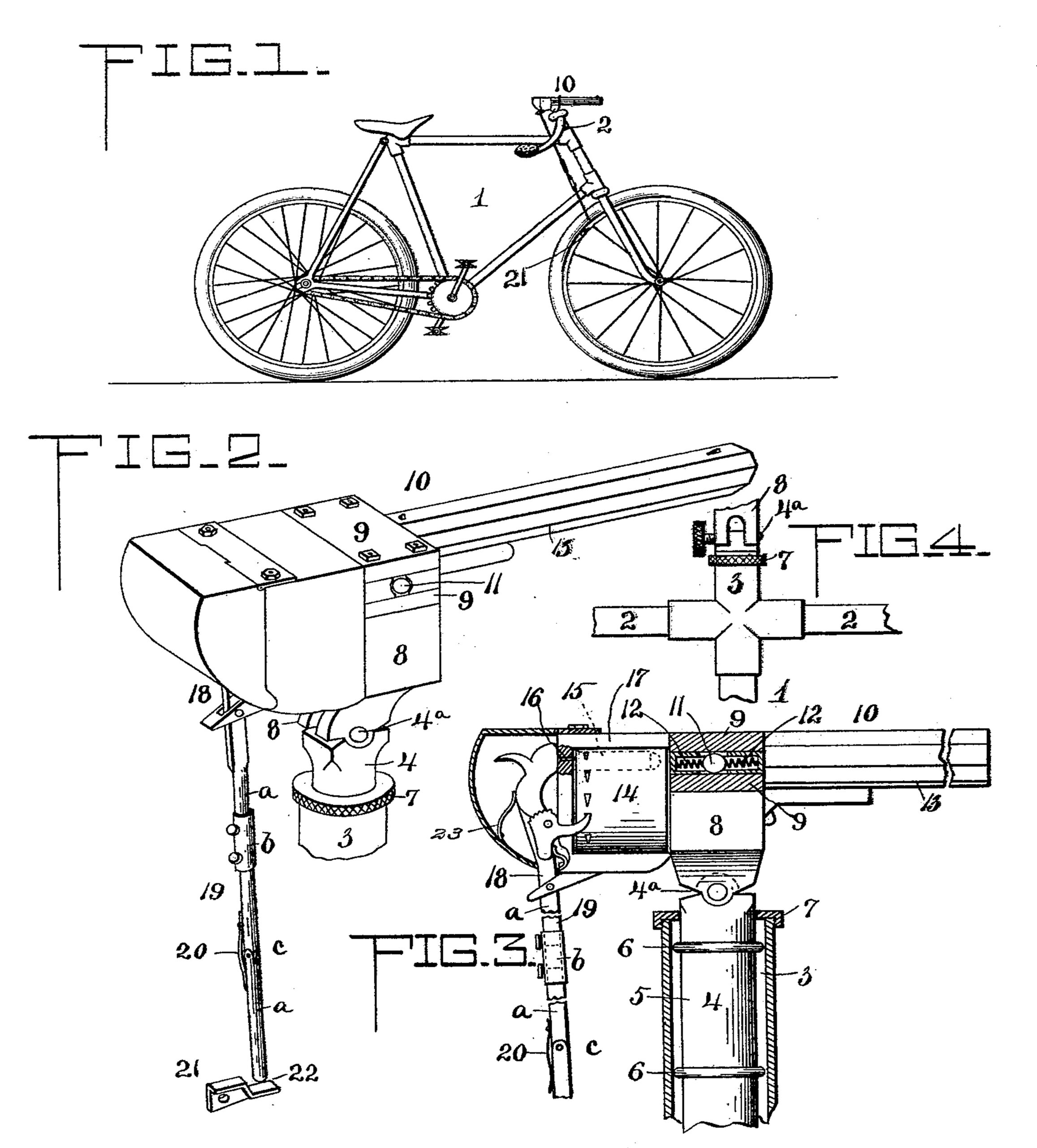
In the drawings, Figure 1 is a side elevation of a bicycle having the herein-described firearm applied thereto. Fig. 2 is a detail perspective view of the firearm and the support therefor removed. Fig. 3 is a transverse section taken through the support with the firearm therein. Fig. 4 is an elevation of the upper end of the socket, with portions broken away and looking in a direction at right angles to Fig. 8.
Referring to the drawings, the numeral 1 designates an ordinary bicycle provided at the head, above the handle-bars 2 thereof, with a socket 3, and swiveled in the said socket is a support 4 for the firearm hereinafter described. The socket 3 comprises an upwardly-extending split sleeve rising above the handle-bars and provided with a screw-collar 7, by means of which the split sleeve is clamped upon the support 4, said support 4 comprising a stem 5, having arranged there on a series of rubber washers 6 or their equivalent, that enter the socket 3. The support 4 just above the collar 7 is hinged, as shown at 4a, the axis of the hinge being transverse, whereby the barrel of the firearm can be elevated and depressed.
The numeral 8 designates a pair of vertically-disposed spaced parallel arms arranged at each side of the support 4 and provided at their upper ends with horizontally-disposed spaced parallel securing-bars 9. Between the pairs of arms 8 is arranged a firearm 10, provided at opposite sides with trunnions 11, and said trunnions are disposed within the space between the horizontal bars 9 of each of the arms 8. Recoil-springs 12 of any suitable construction are arranged at the front and rear sides of the trunnions 11 to take up the jar and break the recoil caused by the firing of the weapon.
The firearm 10 is herein shown as a revolver provided with the usual barrel 13 and a rotating cylinder 14, journaled in close proximity to the rear end of the barrel 13, said cylinder forming a magazine designed to receive a supply of shells 15. A firing-pin 16 is arranged in the rear end of the cylinder-frame 17. The hammer 18 of the firearm is provided with a depending tripping-rod 19, comprising two extensible sections a, each connected by a sleeve or collar b, whereby the tripping-rod can be lengthened to permit the barrel to be raised or depressed, while the lower section a is jointed, as at c, so that it can be thrown to one side when it is not desired that the rod shall be operated by the rotation of the wheel, said lower section being held in place normally by a spring 20. This spring-collar prevents any undue vibration and injury to the parts in the manipulation of the tripping-rod.
The numeral 21 designates an inclined tripping-block secured to the steering-wheel of the bicycle in any suitable manner, and the inclined portion of said block is provided with a depression 22, in which the lower end of the tripping-rod 19 is adapted to enter to cause a sufficiently loud sound to indicate that the hammer is being operated. This sound is similar to the ordinary clicking sound incident to the cocking of a revolver, and as the tripping-block 21 continues its forward movement the rod 19 is released, thereby permitting the hammer 18 to strike the firing-pin 16 and explode the shell within the cylinder.
The operation of the herein-described invention is as follows: The tripping-rod 19 being in the position shown in the drawings, it will be seen that as the steering-wheel of the bicycle rotates the tripping-block 21 will be brought into contact with the lower end of the rod 19, thereby swinging it forward and the hammer 18 backward upon its pivot, and after the passage of the block 21 said hammer will be released, pressed forward by spring 23, and explode the shell immediately opposite the firing-pin 16 in the usual manner and as previously described. This firing operation will continue as the wheel rotates until the supply of shells within the cylinder is exhausted. In firing the recoil will be broken by the spring 13 at the front and rear sides of the trunnions 11, thereby preventing the breakage of the parts and removing the strain thereon.
In the foregoing description it will be observed that the herein-described improvement provides a firearm which is adapted for use upon bicycles, and while shown and described in connection therewith it will also be noted that the same is not restricted to such use, but may be used upon various forms of vehicles. Changes in the form, proportion, and minor details of construction may be resorted to without departing from the spirit or sacrificing any of the advantages of the invention.
Having thus described the invention, what I claim as new, and desire to secure by Letters Patent, is—
1. The combination of a bicycle, a firearm carried thereby, a tripping-rod connected with the hammer of the firearm, and a projection from the side of the wheel of the bicycle for actuating the tripping-rod, substantially as described.
2. In a firearm of the class described, the combination with a vehicle, of a socket carried thereby, a support having a depending stem arranged within said socket, said support being provided with vertically-disposed, upwardly-projecting parallel spaced arms arranged in pairs, a firearm disposed between said pairs of arms and provided with trunnions, horizontally-disposed, parallel, spaced bars arranged in the upper ends of said arms and receiving said trunnions, springs arranged at the front and rear sides-of said trunnions to break the recoil, a depending jointed tripping-rod carried by the hammer of the firearm, and an inclined tripping-block carried by the wheel of the vehicle, and provided with a depression, said tripping-block being adapted to actuate said tripping-rod, substantially as shown and for the purpose described. In testimony whereof I have signed this specification in the presence of two subscribing witnesses.
JAMES HORNER.
Witnesses:
JAMES B. McMEANS,
CONROD STETLER.