
US 652625
UNITED STATES PATENT OFFICE.
CHRISTOPHER D. McDONALD, OF VANCE, COLORADO.
REVOLVER.
SPECIFICATION forming part of Letters Patent No. 652,625, dated June 26, 1900.
Application filed February 9, 1900. Serial No. 4,648. (No model.)
To all whom it may concern:
Be it known that I, CHRISTOPHER D. McDONALD, of Vance, in the county of San Miguel and State of Colorado, have invented a new and useful Improvement in Revolvers, of which the following is a specification.
My invention is in the nature of an improvement upon the revolver for which I have in Made application for Letters Patent of the United States, Serial No. 725,091, which application was filed July 25, 1899, and allowed September 29, 1899. In this application I described and claimed a revolver in which the handle portion is provided with rigidly attached upper and lower extensions inclosing the cylinder-space, and the barrel is hinged on a vertical axis between the forward ends of said rigid extensions and bears the revolving cylinder, which swings out when the barrel is deflected about said joint at the two forward extensions of the handle. My present invention employs this same general principle of construction, but provides an improved means of articulation, as will be hereinafter more fully described with reference to the drawings, in which—
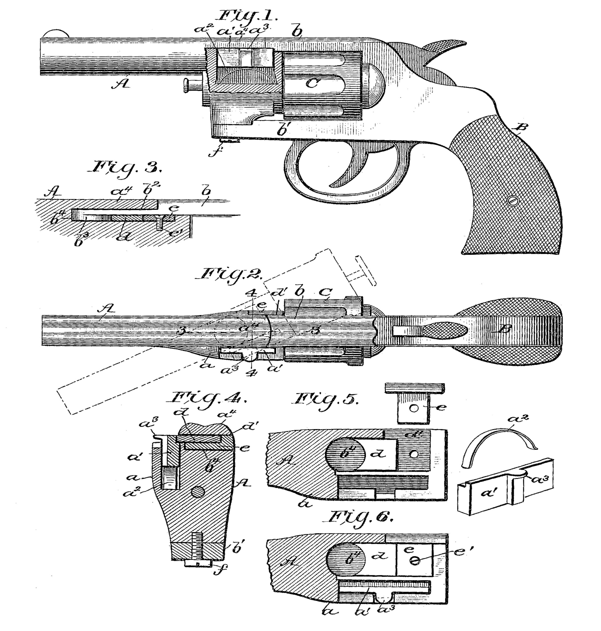
Figure l is a side view, partly broken away. Fig. 2 is a plan view with the barrel turned to one side in dotted lines. Fig. 3 is a partial longitudinal section on line 3 3 of Fig. 2. Fig. 4 is a transverse section through line 4 4; and Figs. 5 and 6 are plan views of the rear portion of the barrel, partly broken away to show the means for jointing the barrel to the handle extensions.
In the drawings, A represents the barrel, carrying the cylinder C, and B is the handle,having rigid forward extensions b and b’, inclosing the cylinder, and to the forward ends of which extensions the barrel is jointed about a vertical axis, as shown and described in my former application referred to.
In my present invention one side of the rear end of the barrel is made with a lateral projection a, in which is formed an elongated chamber opening at the upper edge of the barrel, containing a horizontal locking-bar a’, having a thumb-piece or lip-o1.3 extending through a notched portion of the barrel out to the edge of the same. In the elongated chamber, beneath the locking-bar a, is an elliptical spring a2,which makes the bar spring seated, normally holding it up in locking position to prevent the barrel from being turned on its axis of articulation, but capable of being depressed by the thumb, so as to allow the rear end of the barrel to pass under the forward extension b of the handle.
The articulated joint of the barrel is formed at the lower side by a simple screw f, connecting the lower extension b’ of the handle to the lower lug of the barrel. At the upper side, however, there is a peculiarly-formed joint, as follows: The upper extension b of the handle is recessed at b2 on its upper side, which portion passes under an overhanging part a4 on the rear end of the barrel. The lower side of the extension b is formed at its extreme end with a circular boss b3, which forms the center bearing of the joint and is locked in a chamber b4 in the rear end of the barrel as follows:
A movable block d has a concave front end fitting the boss b3 on the extension b. This block d is slipped into the right-angular recess in the top of the barrel behind the boss b3 by being first inserted through the side opening d’ and is then pushed up to the position shown in Fig. 5. A locking-slide e, Fig. 5, is then slipped sidewise into the opening d’ and when fully in is fastened by a screw e’, as in Fig. 6, and retains the block d, behind the boss or joint-bearing b3. To take the revolver to pieces, the screw e’ is taken out and the slide e and block d removed through the outlet d’, and the screw f of the lower joint being removed the boss or bearing b3 can be drawn back and taken out through the opening d’.
When the barrel is in true alinement, the long locking-bar a’ is forced up by its subjacent spring a2 and by bearing against the side of the upper extension b holds the barrel firmly in alinement, so that it cannot be bent on its joint, and the long bearing which the bar a’ affords makes a very strong lock and holds the barrel firmly in alinement.
In breaking the revolver for ejecting the shells and reloading the handle is taken in the right hand and the barrel in the left, with the thumb of the left hand resting upon the lip a3 of the spring-seated locking-bar, and it will be seen that all the parts are so organized as to enable this action to be quickly and most conveniently effected.
Having thus described my invention, what I claim as new, and desire to secure by Letters Patent, is—
1. A revolver having a handle with a rigid extension beyond the cylinder, and formed with a pivot-boss on its lower side at the end, a barrel having a recessed upper surface at the rear end with a side outlet, a detachable bearing block adapted to be introduced through this side outlet and pushed up to the boss, and a laterally-inserted locking-slide for the bearing-block substantially as described.
2. An articulated joint for a revolver, consisting of a barrel having an overhanging rear end a4 and a right-angularly-recessed chamber beneath it with lateral outlet, a handle extension b with recessed upper surface b2 and boss b3, and the detachable bearing d arranged to be inserted through the lateral outlet and pushed up to contact against the boss, and the locking-piece e inserted laterally behind the bearing d substantially as and for the purpose described.
In testimony whereof I have signed my name to this specification in the presence of two subscribing witnesses.
CHRISTOPHER D. MCDONALD.
Witnesses:
L. C. KINIKIN,
C. H. COULSON.