
US 666476
UNITED STATES PATENT OFFICE.
LEONARD HUNTRESS DYER, OF WASHINGTON, DISTRICT OF COLUMBIA, ASSIGNOR TO FREDERICK B. POPE, OF AUGUSTA, GEORGIA, AND GILES D. MIMS, OF PARKSVILLE, SOUTH CAROLINA.
REVOLVING FIREARM.
SPECIFICATION forming part of Letters Patent No. 666,476, dated January 22, 1901.
Application filed December 14, 1899. Serial No. 740,296. (No model.)
To all whom it may concern:
Be it known that I, LEONARD HUNTRESS DYER, a citizen of the United States, residing at Washington, in the District of Columbia, have invented certain new and useful Improvements in Revolving Firearms; and I do hereby declare the following who a full, clear, and exact description of the invention, which will enable others skilled in the art to which it appertains to make and use the same.
This invention relates to improvements in multiple-action firearms wherein in addition to the usual firing devices a number of shots may be fired by a single retraction of the trigger.
The invention is an improvement on the device invented by Frederick E. Pope, described and claimed in an application filed the 23d day of November, 1899, and numbered serially 738,038.
The invention relates to a revolving firearm, pistol, shotgun, rapid-fire gun, or cannon wherein in addition to the cartridge-carrying cylinder is provided the usual hammer with its operating-spring, in connection with the usual form of trigger with its engaging spring and with spring-actuated means for alternately retracting the hammer and releasing it from such retracted position, so that its spring will bring it into contact with the cartridge with sufficient force to explode the primer thereof. This means for retracting and releasing the hammer consists, preferably, of a disk mounted upon an axis and rotated by a convolute spring. This disk is provided, either upon its periphery or on one of the faces thereto, with a series of pins with equal intervals separating them. These pins may be as many in number as there are chambers in the cylinder of the revolver; but this is not necessary. The periphery of the disk is provided with notches which engage the trigger. It is essential that there be as many notches as there are pins. Sufficient tension being applied to the convolute spring and the trigger being pulled, the disk will revolve and one of its pins will engage with the hammer and retract it. The disk continuing to revolve, the pin will become disengaged and will allow the hammer to be returned by its operating-spring.
So much of the invention as above described is old to me, and to such I make no claim. The following difficulty, however, in the operation of this device has arisen: In order to explode the cartridge with certainty, it is essential that the blow delivered by the hammer shall be forcible, and to accomplish this end the mainspring must be strong. The hammer must therefore move with great rapidity. The convolute spring operating the disk, however, must be strong enough to elevate the hammer against the tension of the mainspring, and the disk will therefore rotate with great speed when released by the trigger. If the disk be located within the stock, it must be of comparatively small diameter, and if provided with six or seven pins the distance separating them must be small. There is therefore considerable danger of an advancing pin striking and engaging with the hammer before the latter has been impelled sufficiently far to reach the cartridge and explode the primer. It is therefore necessary to make the disk of great diameter comparatively, which has some practical objections as, for instance, the need of casings for projecting portions of the disk outside the limits of the conventional stock.
The object of my invention is to overcome this difficulty and provide means whereby a disk of comparatively small diameter may be used, and as soon as the trigger is pulled and the hammer released the disk will not begin to retract the hammer until the cartridge has been exploded. These means are preferably operated by the hammer itself. One arrangement of means may consist in providing a cam projection upon the hammer out to an arc of a circle eccentric to the pivoting-point of the hammer. This cam projection when the hammer is retracted will enter and pass beyond the path of an approaching pin and will stay in the path of such pin until the hammer has been impelled to a position adjacent to the position it assumes when the primer is exploded. As soon as this occurs the cam projection will have come outside of the path of the approaching pin and will allow the same to slip 0d the edge of the cam projection and to advance until it engages with the lifting portion of the hammer. Some distance should separate the edge of the cam portion from the lifting portion of the hammer, and through this space the advancing pin will travel without resistance. The time occupied in traversing this space will be sufficient to allow the hammer to advance beyond its rebounding position and strike the firing-pin and explode the cartridge before the pin engages with the lifting portion of the hammer and repeats the action.
In order to better understand the nature of the invention, attention is called to the accompanying drawings, forming a part of the specification, and in which—
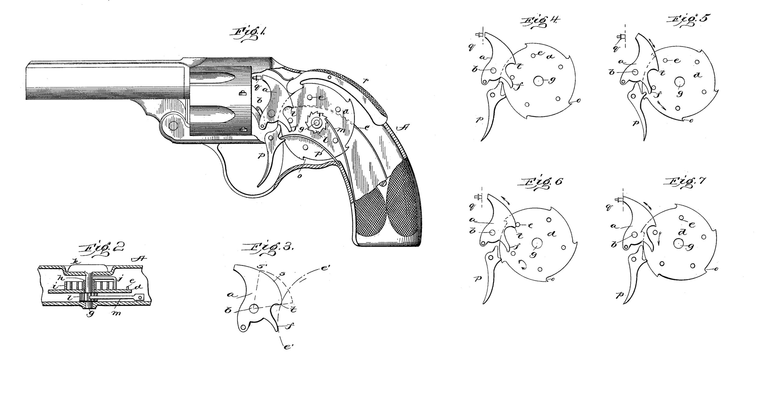
Figure 1 is a side view, partly in section, of a complete weapon of the revolver type. Fig. 2 is a sectional view of the operating-disk. Fig. 3 is an enlarged view of the hammer; and Figs. 4, 5, 6, and 7 are views of the hammer, trigger, and operating-disk in the various positions assumed during the operation of the weapon.
In all the several views like parts are designated by the same letters of reference.
Referring to Figs. 1 and 2, a is a hammer pivoted to the pin b and provided with a main operating-spring c. d is the disk located within the stock A and provided with a series of pins e upon one face thereof. The latter are arranged to engage with the projecting finger f of the hammer. The disk is mounted upon the shaft g by means of the loosely fitting sleeve h. The latter is connected to one end of the convolute spring i, the other extremity of which is fastened to an arm or finger j, rigidly secured to the shaft g. k is the flush key to enable one to give a turn to the shaft and impart tension to the convolute spring. A pawl l and ratchet-spring m serve to keep the parts from retroacting. p is the trigger, which engages with one of the notches 0, formed upon the periphery of the disk d, a spring p’ preventing accidental disengagement. A safety-catch r is provided, if necessary. q is the firing-pin.
Reference being had to Fig. 3, it will be seen that the hammer a is provided with a cam-shaped portion s thereon, ending in a projecting edge t. In its normal position the point t lies within the path e’ e’ of the pins e. However, when the hammer is in engagement with the firing-pin, as shown in Fig. 7, the part t is beyond the path of the pins. The cam portion may be of any shape or configuration, but is preferably made smooth and free from hollows and depressions, so that a pin bearing against it will meet with but small opposition.
The only point necessary in designing the hammer is to arrange that the part or point t shall be no farther removed from the pivoting-point b than any operating part of the cam portion—as, for instance, the part s’.
The operation of the device is as follows: Sufficient tension being applied to the convolute spring i; and the trigger being released, the disk d will turn in the direction of the arrow, as shown in Fig. 5. One pin will engage with the projection f of the hammer and retract it in the direction of the arrow, and the pin slipping off the edge of the projection the hammer will be impelled forward by means of its spring, as shown in Fig. 6, until it strikes the firing-pin and explodes the cartridge. In the meantime the disk continuing to revolve the next pin will engage with the cam portion s of the hammer and the disk will be brought to a standstill. The disk will be retained in an inactive position until the projection p’ clears the path e’ e’ of the pin, when the disk will continue to advance, as shown in Fig. 7. The distance separating the parts t and f is sufficient to allow the hammer to advance beyond the rebounding position and impel the firing-pin forward. The trigger continuing to be retracted, the action will be repeated until all of the cartridges have been exploded.
Having now described my invention, what I claim as new therein, and desire to secure by Letters Patent, is—
1. In a revolving firearm, the hammer and trigger therefor, the spring-actuated disk having a series of projections or pins thereon which may engage seriatim with the hammer and retract and release it, and a projection or cam on the hammer which will block the path of a following pin and render the disk inoperative until the hammer passes the rebounding position.
2. In a revolving firearm, the hammer and trigger therefor, the spring-actuated disk having a series of projections or pins thereon which may engage seriatim with a lifting projection on the hammer and retract and release the same, and a projection or cam on the hammer above the lifting projection which will block the path of a following pin and render the disk inoperative until the hammer passes the rebounding position and will then allow the disk to continue to turn permitting the hammer to advance beyond the rebounding position and explode the cartridge.
This specification signed and witnessed this 8th day of December, 1899.
LEONARD HUNTRESS DYER.
Witnesses:
M. A. McLEOD,
J. F. BEALE.