
US 666555
UNITED STATES PATENT OFFICE.
FREDERICK B. POPE, OF AUGUSTA, GEORGIA, ASSIGNOR OF ONE-HALF TO GILES D. MIMS, OF PARKSVILLE, SOUTH CAROLINA.
REVOLVING FIREARM.
SPECIFICATION forming part of Letters Patent No. 666,555, dated January 22, 1901.
Application filed November 23, 1899. Serial No. 733,038. (No model.)
To all whom it may concern:
Be i t known that I, FREDERICK B. POPE, a citizen of the United States, residing at Augusta, in the county of Richmond and State 5 of Georgia, have invented a certain new and useful Improvement in Revolving Firearms; and I do hereby declare the following to be a full, clear, and exact description of the invention, which will enable others skilled in the art to which it appertains to make and use the same.
My invention relates to multiple-action firearms wherein a number of shots may be fired by a single retraction of the trigger. The invention relates, however, to a revolving fire-arm, pistol, shotgun, rapid-fire gun, or cannon wherein the shots may be red at very small intervals, or, if desired, single-aimed shots may be fired.
The invention broadly consists in providing the usual hammer with its operating spring in connection with the usual form of trigger with its engaging spring and with spring-actuated means for alternately retracting the hammer and releasing it from such retracted position, so that its spring will bring it in contact with the cartridge with sufficient force to explode the primer therein. This means for retraction and releasing the hammer consists of two agencies—first the usual connection with the trigger, and, second, of a disk mounted upon an axis rotated by a convolute spring. This disk is provided either upon its periphery or on one of the faces adjacent thereto with a series of pins, with equal intervals separating them. The pins may be as many in number as there are chambers in the cylinder of the revolver; but this is not necessary. The periphery of the disk is provided with notches which engage the trigger. It is essential that there be as many notches as there are pins. Sufficient tension being applied to the spring and the trigger being pulled, the disk will revolve, end one of its pins will engage with the hammer and retract it. The disk continuing to revolve, the pin will become disengaged and will allow the hammer to be returned by its operating-spring. Means are provided to prevent the weapon from becoming accidentally discharged, which means may consist of a safety-catch arranged adjacent to the palm of the operator’s hand, which catch may be disengaged while aiming the revolver. Means are also provided for giving sufficient tension to the convolute spring, which means may consist of mechanism connected with the barrel, so that when the letter is swung down upon its axis and returned to the tiring position the spring will have received sufficient tension to discharge the weapon as many times as there are chambers in its cylinder.
In order to better understand the nature of the invention, attention is directed to the accompanying drawings, forming a part of specification, and in which—
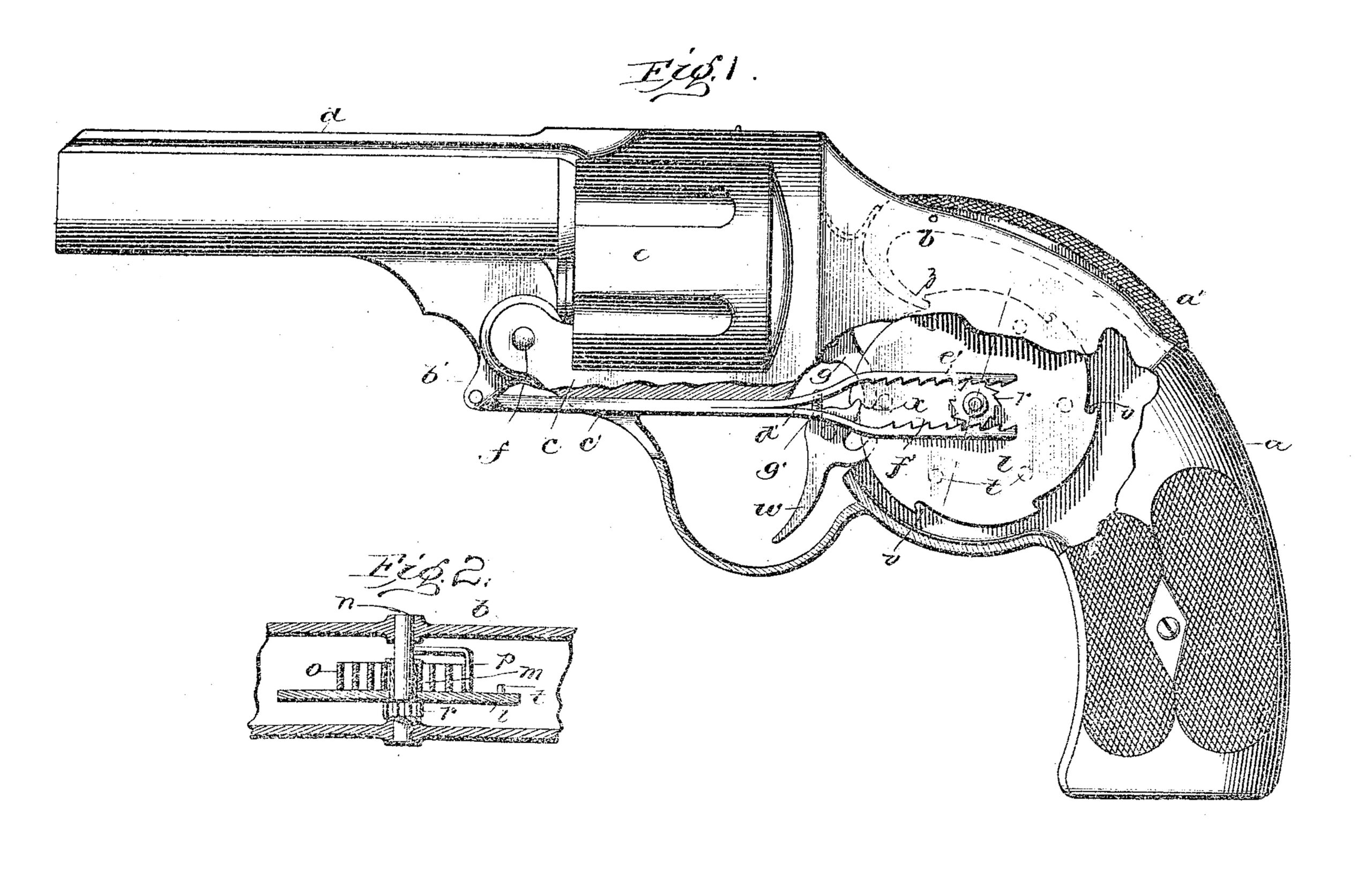
Figure 1 is a side view, partly in section of a revolver; and Fig. 2 is a sectional view of part of the operating mechanism.
In both views like parts are designated by the same letters of reference.
The stock a, the frame b, the fore-frame c, the barrel d, and the cylinder e are of the usual design and construction.
The barrel d is connected to end supported upon the fore-frame c by a horizontal pivot f, so that it with its cylinder e, may be broken down and the used cartridge cases ejected and fresh cartridges inserted in the well known manner.
The hammer g is pivoted to the frame a in the usual manner. It carries the cylinder rotating pawl, as is usual, and is provided with a main or hammer spring, neither of which is shown.
The disk l is mounted upon the sleeve m, (see Fig. 2,) the latter turning freely upon the shaft n, which is mounted in bearings within the frame b. A convolute spring o surrounds part of the sleeve m and is connected thereto at one extremity, the other extremity being fastened to an arm p, which latter is supported upon the shaft n, as shown in Fig. 2.
An arm is rigidly secured either to the barrel d or the pivot f. This arm is indicated by the letter b’. A horizontal arm or pitman c’ is arranged under and parallel to the fore-frame c. The pitman is split or bifurcated at d’, and the inner faces of the two arms, forming the bifurcated portion, are notched at e’ and f’, which notched portions engage, respectively, with the top and bottom faces of the ratchet-wheel r. An adjusting screw g’ may be provided to regulate the tension of the two elastic parts e’ and f’ in engagement with the ratchet, r.
The disk l is provided with a series of pins or other projections t. (Shown in broken lines in Fig. 1.) These pins are arranged to engage, upon the disk being rotated, with the hammer and cause the latter to be retracted then released. To prevent the disk from revolving unless desired, a series of notches v are provided upon its periphery. These notches are equal in number to the pins t and are peripherally arranged adjacent thereto. The trigger w is provided with an engaging finger x which may engage with any of the notches v. The usual trigger spring (not shown) prevents the projection from becoming disengaged. A safety catch z may be provided to engage with one of the notches v, which catch may be disengaged by pressing upon the operating portion a’, arranged at the back of the stock.
The operation of the device is as follows: The pistol is loaded in the usual manner. Sufficient tension is then put upon the spring o. When the barrel and cylinder are broken down for reloading, the arm b’ will be forced to the rear, which will carry the pitmen c’ backward. The teeth of the bifurcated portion f’ will engage with the lower portion of the ratchet r and will turn the same about half of a revolution, the teeth of the ratchet slipping under the teeth of the upper portion e’, it being understood that the parts are sufficiently elastic to allow this to be done. On the action of the revolver being closed, the pitman c’ will be moved forward again, engaging the teeth of the portion e’ with the upper upper face of the ratchet and revolving the same e half-revolution in the same direction. This will apply sufficient tension to the spring o to operate the hammer as many times as there are shots to be fired. The letter is kept from rotating, however, by the engagement of the trigger and the safety-catch. To discharge the weapon, the two latter are simultaneously disengaged, which will allow the disk to rotate in the direction of the arrow. One of the pins t will engage with the projection u on the hammer g and will retract the same against the tension of the spring k until the disk has assumed a position to cause the pin to disengage with the hammer projection. The hammer will then be forcibly brought in contact with the primer of the cartridge. If after the projection x of the trigger w is released from its engaging notch v it will be immediately reapplied to the periphery of the disk l, it will engage with the succeeding notch and the disk will be locked against any further movement until the trigger is again retracted. This will explode but one cartridge. If, however, the trigger and safety-catch be pressed back and kept in that position, the disk will be free to turn and the pins t thereon will successively engage with the projection u or the hammer, alternately drawing the same back and releasing it. The six or seven shots contained in the cylinder of the revolver can then be fired in an exceedingly short space of time.
Having now particularly described and ascertained the nature of my said invention, what I claim as new therein, and, desire to secure by Letters Patent, is—
1. In a revolving firearm, the hammer, the operating-spring therefor, the trigger, spring actuated means for alternately retracting the hammer and releasing it from such retracted position, whereby a plurality of shots may be tired in rapid succession, and means, operated by breaking down of the action, for initially giving tension to said spring-operated mean, substantially as set forth.
2. In a revolving firearm, the barrel, the hammer, the operating-spring therefor, the trigger, a disk engaging with said hammer, by means of which it may be alternately retracted and released from such retracted position, whereby a plurality of shots may be fired in rapid succession, a spring engaging with said disk, a ratchet-wheel connected to said spring, and a serrated pitmen connected to the barrel and engaging with said ratchet, whereby the same will be turned on the breaking down of the action, substantially as set forth.
3. In a revolving firearm, the barrel, the hammer, the operating-spring therefor, the trigger, a disk, engaging with said hammer, by means of which it may be alternately retracted and released from such retracted position, a ratchet-wheel connecting with the said spring, and a bifurcated, serrated pitman connected to the barrel and engaging with opposite sides of said ratchet, whereby the same will be turned a half-revolution by the breaking of the action, and a half-revolution by the closing of the action, substantially as set forth.
This specification signed and witnessed this 4th day of November, 1899.
FREDERICK B. POPE.
Witnesses:
PORTER FLEMING,
J. F. CLECKLEY.