
US 565692
UNITED STATES PATENT OFFICE.
WILLIAM A. RICHARDSON, OF WORCESTER, MASSACHUSETTS, ASSIGNOR TO THE HARRINGTON & RICHARDSON ARMS COMPANY, OF SAME PLACE.
LOADING-GATE FOR REVOLVERS.
SPECIFICATION forming part of Letters Patent No. 565,692, dated August 11, 1896.
Application filed March 28, 1896. Serial No. 585,266. (No model.)
To all whom it may concern:
Be it known that I, WILLIAM A. RICHARDSON, a citizen of the United States, residing at Worcester, in the county of Worcester and State of Massachusetts, have invented a new and useful Improvement in Loading-Gates for Revolvers, of which the following, together with the accompanying drawings, is a specification sufficiently full, clear, and exact to enable persons skilled in the art to which this invention appertains to make and use the same.
The objects of my present invention are, first, to provide a revolver having a recoil-shield with a loading-gate located within said shield; second, to combine the loading-gate with the recoil-shield in such manner that the shield will afford support for the gate when in closed position; third, to afford facilities for the convenient operation and retention of the loading-gate at its several adjustments in an efficient and desirable manner, and, fourth, to provide the loading-gate located within the recoil-shield with a forwardly-protuberant face in line with the loading-way, as more fully hereinafter explained. These objects I attain by the mechanism illustrated in the drawings, wherein—
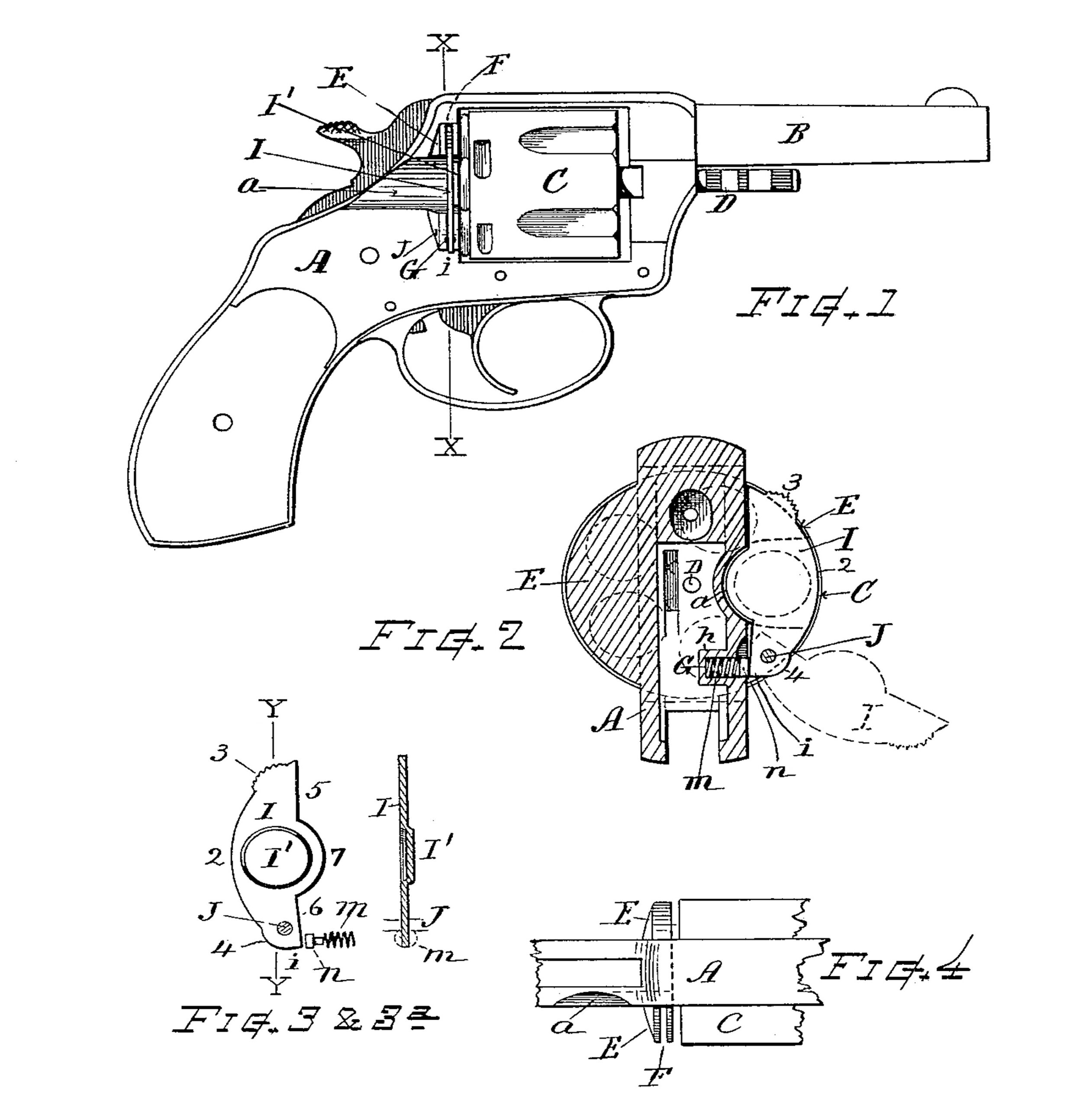
Figure 1 is a side view of a revolver embodying my invention. Fig. 2 is a vertical section at line X X, drawn to somewhat larger scale. Fig. 3 is a separate front view of the loading-gate and its spring devices. Fig. 3a is a section of the same at line Y Y; and Fig. 4 is a top view of a portion of the frame, showing the recoil-shield as recessed for receiving the loading-gate.
This invention is an improvement applicable to solid-frame revolvers, or to that class in which the recoil-shield or laterally-projecting guard in rear of the cylinder is provided with a channel or loading-way at the side of the frame to facilitate the introduction of the cartridges into and the removal of the shells from the cylinder-chamber in well-known manner; and my invention consists in the loading-gate constructed and combined with the recoil-shield for operation substantially in the manner shown and described, and as definitely pointed out in the summary.
Referring to parts, A denotes the frame of the revolver, B the barrel, and C the cylinder, which is arranged within the frame to revolve about the center-pin D in well-known manner.
E indicates the recoil-shield, consisting, as usual, of laterally-projecting semicircular flanges integrally formed upon the sides of the frame in rear of the cylinder.
The recoil-shield at the right-hand side of the frame, in which is formed the loading-way a, is provided with a vertical recess or slit F cut therein, the inner limit of said recess being on a line flush, or nearly so, with the side of the frame in that part above the channel, while said recess extends inward somewhat farther at its lower part, as indicated in Figs. 2 and 4. A small hole G for containing a spring is bored into the frame near the lower end of the slot, the frame being thickened or provided at that part with a boss h on its inner side to prevent the hole cutting through into the interior space.
I indicates the loading-gate, which consists of a thin plate of metal adapted to fit into the recess F, and having its outer edge formed with a circular contour corresponding to the circle of the cylinder or recoil-shield. It is provided with a serrated prominence 3 near its upper end and a rounded prominence 4 near its lower end, while its inner edge is formed with straight portions 5 and 6 and a central inwardly-projecting portion 7, that matches with the rounded channel a in the frame. The loading-gate I is located within the recess in the recoil-shield and hinged or pivoted therein by a pin J, that extends through the shield and gate near the lower end thereof, parallel with the cylinder-axis, so that the gate can swing outward and downward, as indicated by dotted lines on Fig. 2. A small coiled-wire spring m and spring-pressed n stud are arranged in the hole G under the heel i of the gate to act thereon by outward pressure for normally retaining said gate when in closed position and to hold said gate open when the angle of the heel has swung inward past the stud. The rounded prominence 4, resting on the stud or spring, retains the gate at any open position, but when the heel passes the center of the stud n the loading-gate snaps into closed position at once by pressure of the spring.
The front side of the gate, at a position corresponding to the loading-way channel a, is best provided with a projecting part or protuberant disk I’, the offset dimension of which corresponds with the thickness of the metal in that portion of the recoil-shield forward of the vertical recess F. This brings the disk-face I’ sufficiently forward of the flat end portions of the gate, so that its central face lies approximately in the same plane with the face of the recoil-shield to serve as a guard for preventing rearward displacement of the cartridges as the cylinder-chambers revolve past the loading-way when the revolver is used in upward firing, or at any time when the loading-gate is closed. Said projection I’ is preferably made by stamping or punching forward without detaching a portion of the metal plate of the gate, as indicated in Figs. 3 and 3a, thus producing a comparatively strong and desirable gate of very thin metal, one that will occupy but little space in the recoil-shield, and which can be manufactured with facility and at moderate cost; but if in any instance preferred, the projection can be made by fixing a disk or reinforce-piece upon the face of the gate-plate.
In the operation the loading-gate is opened by placing the thumb upon the serrated prominence 3 and swinging its top end outward from the recess in the shield sufficiently to open the channel a. The shells can then be removed and the cartridges inserted in the usual way. The loading-gate may then be snapped back into closed position, where it is retained with the edge 5 pressed against its seat within the recess of the recoil-shield by the force of the spring m or spring-pressed stud acting against the heel of the gate below the pivot-center of the hinging-pin.
This loading-gate can be made of comparatively thin metal, since it is embraced and. sustained against backward or forward displacement by the projecting portions of the recoil-shield, within which it is located, both above and below the loading-way a, while it can be conveniently opened and closed, as desired.
I am aware that loading-gates of different construction have been heretofore employed in revolving firearms, and I do not, therefore, broadly claim a loading-gate irrespective of its construction, arrangement, or mode of operation.
What I claim, and desire to secure by Letters Patent, is—
1. In a revolver, the revolver-frame having, upon the side thereof, an integral laterally projecting recoil-shield, with the loading-way therethrough, the projecting portions of said recoil-shield, above and beneath said loading-way, slotted or recessed transversely to the loading-way channel, and a loading-gate across said channel, located within the recoil-shield and removably supported in said recessed projections.
2. In combination, with a revolver-frame provided with the loading-way channel in its side, and having its recoil-shield slotted parallel with and slightly back from the front face thereof; a loading-gate disposed within the recoil-shield and consisting of a plate adapted for support across the loading-way with its end fitting the slot in said recoil-shield, and provided upon its front side with a protuberant face, at the position of the loading-way channel, for the purpose set forth.
3. A loading-gate for revolvers, formed of thin plate metal and consisting of a flat blade having at its central part a forwardly-protuberant face offset from the plane of the surrounding blade-surface, substantially as and for the purpose set forth.
4. The combination, with the revolver-frame provided with the loading-way and the recoil-shield having the vertical slot or recess therein, of a loading-gate located within said recoil-shield and pivoted to swing outward therefrom, and a spring disposed beneath the heel of said gate, for the purpose set forth.
5. In a revolver, in combination with the cylinder, and the frame having a loading-way at the side thereof; the recoil-shield provided with a vertical slit or recess therein, the loading-gate comprising a thin plate of metal fitting within said recess and across the loading-way, and pivoted to swing outward there- from, the pivot-pin arranged through said shield and gate near the end thereof, and the spring of coiled wire and spring-pressed stud disposed within a hole in the frame under the heel of said loading-gate, substantially as set forth.
6. The loading-gate having the rounded outer edge with the serrated prominence 3, the rounded prominence 4, the angular heel 2, the inward projection 7, and the forwardly-projecting face I’, in combination with the revolver-frame having the recoil-shield, the pivot connecting said loading-gate and recoil-shield, and the spring and spring-pressed stud beneath the heel of the gate, substantially as set forth.
Witness my hand this 26th day of March, 1896.
WILLIAM A. RICHARDSON.
Witnesses:
CHAS. H. BURLEIGH,
ELLA P. BLENUS.