
US 615467
UNITED STATES PATENT OFFICE.
ARTHUR CREED WRIGHT, OF WORCESTER, MASSACHUSETTS, ASSIGNOR TO THE FOREHAND ARMS COMPANY, OF SAME PLACE.
REVOLVER.
SPECIFICATION forming part of Letters Patent No. 615,467, dated December 6, 1898.
Application filed July 29, 1898. Serial No, 687,198. (No model.)
To all whom it may concern:
Be it known that I, ARTHUR CREED WRIGHT, a citizen of the United States, residing at Worcester, in the county of Worcester and State of Massachusetts, have invented certain new and useful Improvements in Revolvers, of which the following is a specification.
My invention relates to revolvers, and particularly to that class of revolvers which are double-acting and self-cocking, and more particularly to that part of the mechanism of the revolver ordinarily known as the “cylinder-stop,” the office of which is to hold the revolving cylinder rigidly in line with the barrel when the revolver is not in use and when it is fired.
The object of my invention is to provide a cylinder-stop of very simple construction and which is positively moved into operative position by the trigger, the upper edge or surface of the trigger in its forward normal position and in its backward firing position engaging the cylinder-stop and positively moving it into its operative position to extend into a notch in and lock the cylinder.
My invention consists in certain novel features of construction of my cylinder-stop mechanism for revolvers, as will be hereinafter fully described.
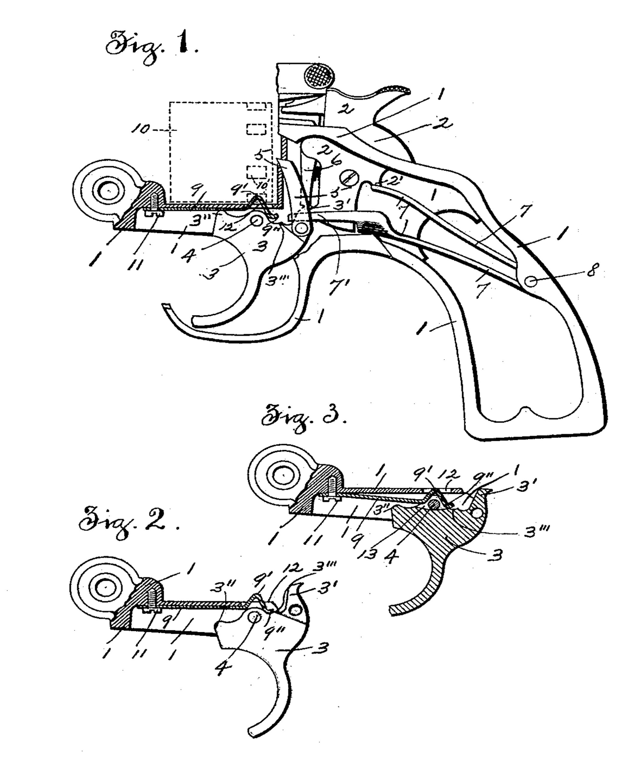
Referring to the drawings, Figure 1 is a side view, partly in section, of a revolver-frame and cocking, firing, and cylinder-stop mechanisms embodying my improvements, showing the trigger in its forward normal position. The cylinder is shown by dotted lines and the cylinder-stop in section. The barrel portion is not shown. Fig. 2 shows a detached portion of the frame and the cylinder-stop in section and the trigger in its rear position when the revolver is fired; and Fig. 3 corresponds to Fig. 2, but shows the trigger in section in its intermediate position, with the cylinder-stop extending in a recess in the upper edge of the trigger and out of engagement with the cylinder: (Not shown.)
In the accompanying drawings, 1 is the frame of a revolver, within which are assembled the several parts of the cocking and firing mechanism.
2 is the hammer, and 3 the trigger, pivoted on a pin 4 and having the pawl 5, which engages the ratchet-teeth on the rear end of the cylinder to revolve the same in the ordinary way, pivoted at its lower end on the upper end of the trigger 3 on one side thereof.
6 is the cocking-lever, pivoted at its upper end in the front portion of the hammer 2 and adapted at its lower end to be engaged by the projection 3’ on the upper rear end of the trigger 3 when the trigger is moved backward to cock the hammer.
All of the above-mentioned parts are of the ordinary construction and operation.
The hammer-spring 7 is made double and in the form of a two-leaf spring and is held in position in the frame by the pin 8. The free end of the upper leaf of the spring 7 extends under and engages a shoulder 2’ on the hammer 2 to actuate the hammer and fire the revolver when the cocking-lever 6 is disengaged from the trigger 3 in the backward movement of the trigger in the ordinary way.
The lower leaf of the spring 7 has a side extension 7’, which extends at one side of the hammer 2, with its forward free end extending in a groove or recess (shown by dotted lines, Fig. l‘inthe pawl 5. The lower leaf of the spring 7 acts to move the trigger 3 to its forward position (shown in Fig. 1) after the revolver has been fired.
The cylinder-stop 9 is preferably made of a flat piece of spring-wire, which extends in a recess in the frame directly below the revolving cylinder 10. The forward end of the stop 9 is secured in this instance by a screw 11 in the frame 1, and the wire is bent so that the normal position of the stop will be that position shown in Fig. 3. The rear free end of the wire or stop 9 is bent, as shown, to form an upward projection 9’, which extends through an opening 12 in the frame and is adapted to extend into a notch 10’ in the cylinder to hold or lock the same.
The extreme end 9” of the stop 9 extends downwardly and rearwardly and is slightly curved to ride on the upper surface or edge of the trigger 3 at the rear of its pivot-point. The upper edge of the trigger 3 has a knob or projection 3” on its top front edge to engage with the body of the stop 9, as shown in Fig. 1, when the trigger is in its forward or normal position and move the stop into its upper position, with the projection 9’ extending into a notch in the cylinder.
The trigger 3 has a recess 3’’’ in its upper edge at the rear of its pivot-point, which engages with the free end 9” of the stop 9 and moves said stop into its upper position and into the notch in the cylinder, as shown in Fig. 2, during the movement of the trigger toward its rear position and before the pistol is fired.
It will be seen that the front end of the lower leaf of the spring 7, acting on the trigger 3, will move said trigger into its forward position (shown in Fig. 1) and cause the knob or projection 3” thereon to engage and positively move the stop 9 into its upper position to cause the extension 9’ thereon to extend into the notch in the cylinder, and when the trigger is in its rear position the recess 3’” in the upper edge of the trigger will engage and positively move the stop 9 into its upper position to cause the extension 9’ to extend into the notch in the cylinder. The cylinder is therefore locked and prevented from moving when the revolver is not in use, and is also locked when the revolver is fired.
When the trigger is in its intermediate position, as shown in Fig. 3, between the forward and rear positions, the free end of the stop 9 by the downward spring action of the stop is moved down into a recess 13 in the upper edge of the trigger 3, (see Fig. 3,) so that the projection 9’ will move out of the cylinder-notch and allow the cylinder to be revolved preparatory to firing the revolver.
The advantages of my improvements in revolvers will be readily appreciated by those skilled in the art.
The cylinder-stop is of very simple construction, and it is positively operated to extend into the cylinder-notch both at the forward and rear position of the trigger by the engagement of the upper edge of the trigger therewith.
It will be understood that the details of construction of some of the parts of my mechanism may be varied, if desired.
Having thus described my invention, what I claim as new, and desire to secure by Letters Patent, is—
1. In a revolver, the combination with the trigger and the spring which moves the trigger into its forward position, of a cylinder-stop made of a flat piece of spring-wire which extends in a recess in the frame above the trigger, and below the revolving cylinder, and has an upward projection to extend into the notches in the cylinder, and its rear free end bent downwardly to be engaged by the upper edge of the trigger at the rear of its pivot-point, to positively move the stop into its operative position, before the pistol is fired, the front upper edge of the trigger engaging the body of the stop, to move the stop into its operative position after the revolver is fired and the trigger returned to its normal position, substantially as shown and described.
2. In a revolver, the combination with the trigger, having bearing-surfaces for the cylinder-stop, both in front and in rear of its pivot-support, the pawl which revolves the cylinder pivoted thereon, and. the spring which actuates the trigger to return it to its normal position, of the cylinder-stop made of a flat piece of spring-wire, which extends in a recess in the frame above the trigger and below the cylinder, and has a projection thereon to extend into the notches in the cylinder, and is positively operated to be moved into its operative position to stop the cylinder, by the engagement of the upper edge of the trigger therewith at the front of, and at the rear of its pivot-support, substantially as shown and described.
ARTHUR CREED WRIGHT.
Witnesses:
J. C. DEWEY,
M. J. GALVIN.