
US 561963
UNITED STATES PATENT OFFICE.
HOMER M. CALDWELL, OF WORCESTER, MASSACHUSETTS, ASSIGNOR TO MARY E. JOHNSON, OF FITCHBURG, MASSACHUSETTS.
REVOLVER.
SPECIFICATION forming part of Letters Patent No. 561,963, dated June 16, 1896.
Application filed May 2, 1896. Serial No. 647,846. (No model.)
To all whom it may concern:
Be it known that I, HOMER M. CALDWELL, a citizen of the United States, residing at Worcester, in the county of Worcester and State of Massachusetts, have invented a new and useful Improvement in Revolvers, of which the following, together with the accompanying drawings, is a specification sufficiently full, clear, and exact to enable persons skilled in the art to which this invention – appertains to make and use the same.
The object of my present invention is to provide a revolver-frame formed with solid cheeks and having a top opening to facilitate machining or cutting out the interior of the frame for the reception of the lockwork, and also provided with a conveniently removable top cap that bridges over said opening and conceals the hammer, the two sides of the cap forming parts of the opposite side surfaces and secured to the frame as more fully described.
Another object is to provide a revolver with a frame having a top opening fitted along its upper edges with shoulders or offsets formed on a circular contour, in combination with a top cap having its edges fitted to rest upon and match said shoulders, whereby the cap is supported against lateral looseness and in proper elevation above the hammer.
Another object is to provide a hammer having its face provided with two contact-ears adapted to strike the seat or frame at either side of the firing-pin, and to render the hammer-top low in position, thus permitting the top covering-cap to be formed below the top line of the frame. I attain these objects by a revolver mechanism constructed as hereinafter explained in detail, and shown in the drawings, wherein—
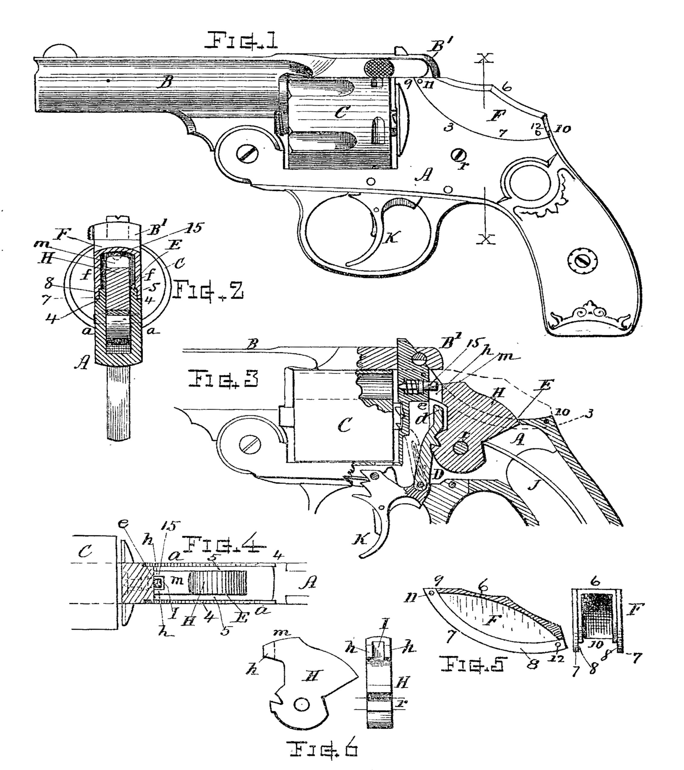
Figure 1 is a side view of a revolver embracing my invention. Fig. 2 is a transverse section at line X X. Fig. 3 is a longitudinal vertical section with the top cap removed. Fig. 4 is a horizontal section showing the top of the frame and hammer. Fig. 5 shows a longitudinal section and front end view of the cap, and Fig. 6 shows the side and front of the hammer.
Referring to parts, A denotes the frame, B the barrel, and C the cylinder, relatively disposed in the usual manner and having combined therewith suitable or well-known means for effecting rotation of the cylinder, opening and closing the arm, ejecting empty shells, and such devices as are usually employed in revolvers, which will be fully understood, but not being features of my present invention need not be herein particularly described.
In accordance with this invention the frame A is made with solid cheeks or sides a and with a top opening E, through which convenient access is afforded for machining and fitting the interior of the frame for the hammer-seat and reception of the lockwork, which latter is preferably of the form shown in Fig. 3. The top of the frame is best cut away at both sides in uniform opposite relation, and preferably on the line of a circular curve, as at 3, the edges fitted with an inward offset or shoulder 4 and upwardly-projecting lip 5, extending from the top of the frame 9 to the rear part 10 thereof, as indicated. Combined with this open-top cutaway frame I provide a removable top cap F, that bridges over and closes the opening, said cap corresponding in width to the lateral width of the frame and extending from the under side of the barrel latch-bar B’ to the position 10 in rear of the hammer H.
The top 6 of the cap is arched to cover the hammer-head in its line of movement, and the sides f f are disposed flush with the sides a of the frame. (See Fig. 2.) The lower edges 7 are dressed off on a circular curve and reduced to form the lip 8, that matches the curved edges 3 and shoulders 4 of the frame, over and upon which the edges of the cap fit and rest, while the ends of the cap fit the frame at 9 and 10, respectively, thus affording a complete closure and finish for the top of the frame, concealing the hammer, and showing a neat and smooth exterior surface at the sides.
Small pins 11 and 12, arranged through-holes in the lip 8 and frame at the upper and lower ends of the cap, serve for retaining the cap securely in position, or, if in any instance preferred, other suitable fastening devices may be used in lieu of said pins.
By forming the frame as shown with the edges 3 and 4 on the line of a circular arc, the construction and the process in manufacture are greatly facilitated and simplified in labor and machining operations, and the accurate fitting of the frame and cap to each other is rendered practically simple and rapid; also, by forming the edges to intermatch in the manner specified, perfect fit and support for the cap laterally is attained, so that the opposite outer faces on the dependent sides f of the top cap and the outer surfaces of the frame-cheek are maintained positively flush or in proper relation to each other.
The hammer H is arranged in the top opening and pivoted, as usual, between the cheeks, as at r. This hammer H, according to my improvement, is formed broader than usual and with a low rounded top, as at m, Fig. 6, and. provided with a bifurcated striking-face, that presents two contact-ears or forwardly projecting side portions h, that strike the hammer-seat e at the right and left of the firing-pin head 15, and with an intervening space or vertical recess I between said ears h, that receives, without touching the firing-pin 15 when in normal condition of inaction, and into which space the end d of the lifter-bar D is interposed when the trigger K is drawn back and the hammer thrown down by the mainspring J, the lifter end d then occupying the space and causing the projection of the firing-pin for discharging the cartridges. By the bifurcated construction of the hammer face, as shown, in connection with the lifter end, the hammer is rendered comparatively low in height, and this hammer can be employed with the top m on line with or below the upper part of the firing-pin, thereby facilitating the use of a low top cap F for concealing the hammer and closing the top of the frame without extending the cap above the bottom line of the barrel-strap B’.
It will be understood that the idea of interposing the end of a lifter between a hammer face and firing-pin as a means for giving projective movement to the latter is not, broadly, a feature included as part of the present invention, since this invention relates to the improved structure of the parts in combination, as defined.
I claim as my invention and desire to secure by Letters Patent—
1. The revolver-frame formed as described, with solid cheeks, cut away at the upper part and having a top opening through which the hammer can be introduced; and a removable top cap fitting over and closing the hammer opening; said cap composed of an arched top portion, the full width of the frame, with two integral, downwardly-extending opposite side portions, as shown, that match the respective cheeks, and form parts of the two side faces of the frame, as set forth.
2. In a revolver, the frame formed with the solid parallel cheek portions, and provided with a central hammer-space opening in its top, and having the upper edges of said cheeks, adjacent to said opening, cut away on the line of an inward circular arc, and fitted along such circular arc, with shoulders or bearing lips, as shown; in combination with the removable top cap bridging over said opening above the hammer-space, and extending rearward from the under side of the barrel latch-bar to a position in rear of the hammer, the two sides of said top cap depending to form parts of the parallel cheek-surfaces, and fitted with circular curved edges that match the circular edges on the frame-cheeks, and suitable pins or fastening devices for securing said cap to the frame, substantially as set forth.
3. In a revolver, the combination of the frame having solid side cheeks and open top, the low-topped hammer pivoted in the opening between said cheeks, its face provided with projecting contact-ears and an intervening recess, the top cap bridging and covering the hammer, its sides flush with and supported upon the cheeks at opposite sides of the frame, the firing-pin fitted in the frame, the trigger, and the hammer-actuating bar having an extended end adapted for the interposition within the hammer-face recess for contact with the firing-pin, all substantially as set forth.
Witness my hand this 29th day of April, A.D. 1895.
HOMER M. CALDWELL.
Witnesses:
CHAS. H. BURLEIGH,
ELLA P. BLENUS