
US 600337
UNITED STATES PATENT OFFICE
WILLIAM A. RICHARDSON, OF WORCESTER, MASSACHUSETTS; MARY A.
RICHARDSON, EXECUTRIX OF SAID WILLIAM A. RICHARDSON, DECEASED,
ASSIGNOR TO THE HARRINGTON & RICHARDSON ARMS COMPANY, OF SAME PLACE.
SAFETY DEVICE FOR FIREARM-LOCKS.
SPECIFICATION forming part of Letters Patent No. 600,337, dated March 8, 1898.
Application filed August 14, 1897. Serial No. 648,231. (No model.)
To all whom it may concern:
Be it known that I, WILLIAM A. RICHARDSON, a citizen of the United States, residing at Worcester, in the county of Worcester and State of Massachusetts, have invented a new and useful Improvement in Lock Mechanism for Revolvers, of which the following, together with the accompanying drawings, is a specification sufficiently full, clear, and exact to enable persons skilled in the art to which this invention appertains to make and use the same.
The objects of my present invention are, first, to provide a safety mechanism applicable to revolvers wherein the hammer is furnished with an integral forwardly-projecting nose for impingement directly upon the cartridge as well as for those in which a firing-pin or detached striker is employed; second, to provide in combination with the frame and lock mechanism, in a double-action or self-cocking revolver, a movable chock or clog consisting of a bar or finger having its lower end pivoted to the rear part of the trigger-head in conjunction with the hammer-lifter pawl and its head extended above said lifter-pawl and normally interposed as an obstruction between the frame and hammer below its striker point or face, and a cavity or recess in the frame or hammer-front into which the head of said chock is elevated to avoid its interference with the full movement of the hammer when the trigger is drawn back and the lifter-pawl thereby raised to the position at which it throws off from the notch in the hammer in the normal discharge of the cartridge, as more fully hereinafter explained. These objects I attain by the mechanism illustrated in the drawings, wherein—
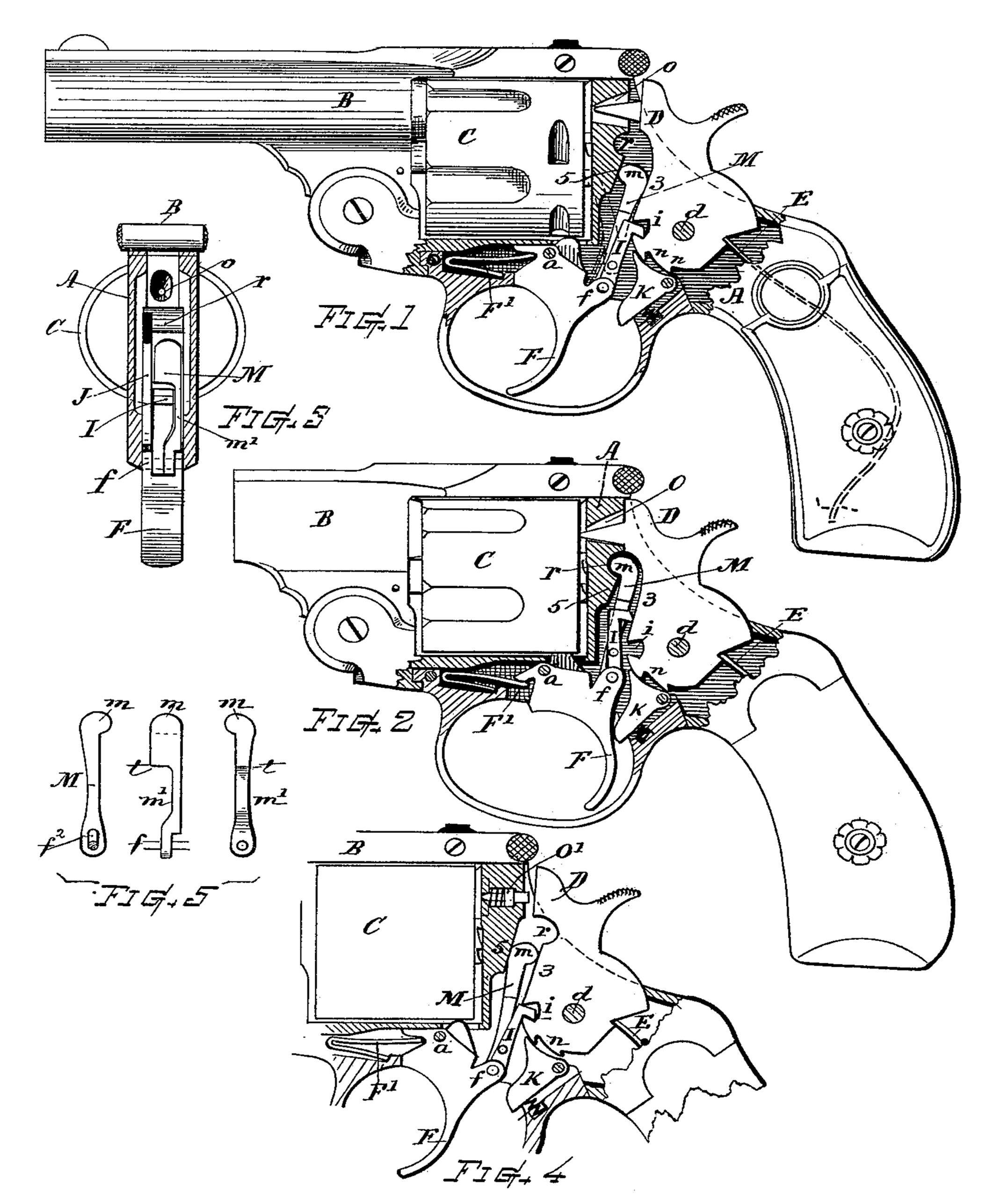
Figure 1 is a side view, partly in section, of a revolving firearm embodying my invention, showing the parts of the lock mechanism in their normal idle positions. Fig. 2 is a similar view showing the parts in position as at the instant of discharge. Fig. 3 is a transverse section at a position in rear of the trigger and lifter pawl and forward of the hammer. Fig. 4 is a view illustrating my invention as applied to a revolver having a firing-pin and with the shock-relieving recess formed in the hammer-breast, the position of the parts corresponding to that of Fig. 1; and Fig. 5 shows the rear and side views of the chock-piece separate from the other parts.
My present invention is equally applicable to revolvers in which the hammer is provided with a long pointed nose for discharging the primer in the cartridge or to those having a detached striker or firing-pin arranged through the recoil-plate.
In general construction the various parts of the revolver which are not herein specifically described may be of any well-known or suitable kind adapted for the operation in connection therewith of the improved mechanism which is embraced in the present described invention. Referring to parts, A denotes the frame; B, the barrel; C, the cylinder; D, the hammer, swinging upon the pivot d and actuated by the mainspring E in usual manner.
F indicates the trigger, pivoted in the frame at a and normally held at forward position by the spring F’ and carrying pivoted to the rear end of its head at f the hammer-lifter pawl I, that engages by its offset top end with the notch i in the tumbler of the hammer for a double action, and having pivoted to the side thereof the cylinder-actuating pawl or hand J, while K indicates the sear, pivoted beneath the tumbler and adapted to engage the, cock notch or notches n therein, all in well known manner of operation.
My invention provides a movable chock, stop-block, or clog device consisting of the bar or finger M, arranged between the frame and hammer, the upper end of its body disposed above the lifter-pawl and terminating at a position below the striker-opening o or firing-pin seat, preferably with a rounded protuberant head m, while its shank m’ extends down at one side of the lifter-pawl I and is pivotally connected with the head of the trigger at f, together with said lifting-pawl, in such manner that the swinging of the trigger will raise and lower said chock M within the lock-chamber.
The breast of the hammer is formed with a plain bearing-surface at 3, and the frame is fitted with an opposite bearing-surface at 5, preferably inclined, as shown, while the upper portion of the chock is made in such form and dimension that it will work up and down between the rear side 5 of the recoil-base and the lower front part 3 of the hammer when said hammer stands at its rebound position or with its face or nose at amply safe distance away from the point of discharge, said chock forming a solid obstruction or clog between the hammer-front and frame so long as said block remains in normal or depressed position, (see Fig. 1,) there serving to positively arrest any forward movement of the hammer at a position of safety and to prevent its nearer approach to the point of firing contact with the striker, firing-pin, or cartridge. A cavity or recess r is provided below the striker opening or hammer-face seat and at a position corresponding with the high position to which the head m of the chock is raised by the extreme backward movement of the trigger, which recess affords sufficient room for the reception of the head m, allowing the chock to take a position where it can stand without its interfering with the hammer in making its stroke fully down upon the discharging-point or firing-pin. (See Fig. 2.) The chock returns to its normal position of safety when the trigger is released.
The recess r is preferably formed in the metal of the frame A; but in other instances, if preferred, it may be cut out from the front edge of the hammer, (see Fig. 4,) just below the contact face or nose, the projection m of the chock M being arranged either at the front or rear side to correspond with the particular disposition of the recess. The nature and operation are substantially the same in each case.
The chock is best made with an offset or shoulder, as at t, above the lifter-pawl and with an arrow shank that extends down alongside of and is hinged to the trigger-head in conjunction with said lifter-pawl, thus affording ample width to the heads of both the lifter and chock devices.
The safety position being made coincident with the limit of rebound action imparted to the hammer by the usual rebound facilities, the chock catches the hammer at the position of rebound and there sustains the position without backlash or looseness between the parts when in normal idle position, thus avoiding any rattling or shake of the parts that might otherwise occur.
What I claim as my invention, and desire to secure by Letters Patent, is—
1. In a revolver, the combination, with the frame having the contact-surface below the striker-opening, the pivoted hammer having the striker face or point the breast-surface and a lifter-notch therein, and the trigger having the hinging head carrying the hammer-lifting pawl; of the safety-chock consisting of a bar arranged between said hammer and frame, its head disposed above the lifter-pawl,its shank extended adjacent thereto and its lower end pivoted, together with said lifter- pawl, to the rear part of the trigger-head, and the recess 7 into which the chock-head is received when the trigger is drawn backward and the chock and lifter raised to a position at which the lifter throws off from the hammer-notch, substantially as hereinbefore described.
2. In a double-action revolver, the combination with the frame, the pivoted hammer provided with the lifter-notch and striking point, the trigger having the hinging head, and the lifter-pawl; of the safety device M having its shank pivoted to said trigger-head at f, and extending upward at the side of said lifter-pawl and its head portion m when depressed forming a chock or obstruction between the frame and hammer-breast in dimension approximately corresponding to the rebound movement of said hammer, and a relieving recess or enlargement r of the intervening space into which the head of said chock is elevated by the drawing back of the trigger, all substantially as and for the purpose set forth.
Witness my hand this 12th day of August, 1897.
WILLIAM A. RICHARDSON.
Witnesses:
CHAS. H. BURLEIGH,
GEORGE F. BROOKS.