
US 612071
UNITED STATES PATENT OFFICE.
PERCY WAREHAM, OF BROOKLYN, MICHIGAN.
REVOLVER.
SPECIFICATION forming part of Letters Patent No. 612,071, dated October 11, 1898.
Application filed July 23, 1897. Serial No. 645,694. (No model.)
To all whom it may concern:
Be it known that I, PERCY WAREHAM, of Brooklyn, in the county of Jackson and State of Michigan, have invented certain new and useful Improvements in Revolvers; and I do hereby declare the following to be a full, clear, and exact description of the invention, such as will enable others skilled in the art to which it appertains to make and use the same.
The invention relates to improvements in revolvers.
The object of the present invention is to improve the construction of revolvers and to provide one which may be conveniently loaded and in which the break of the barrel will be controlled by efficient locking devices.
The invention consists in the construction and novel combination and arrangement of parts, as hereinafter fully described, illustrated in the accompanying drawings, and pointed out in the claims hereto appended.
For a full understanding of the merits and advantages of the invention reference is to be had to the accompanying drawings and the following description.
The improvement is susceptible of various changes in the form, proportion, and the minor details of construction without departing from the principle or sacrificing any of the advantages thereof, and to a full disclosure of the invention an adaptation thereof is shown in the accompanying drawings, in which—
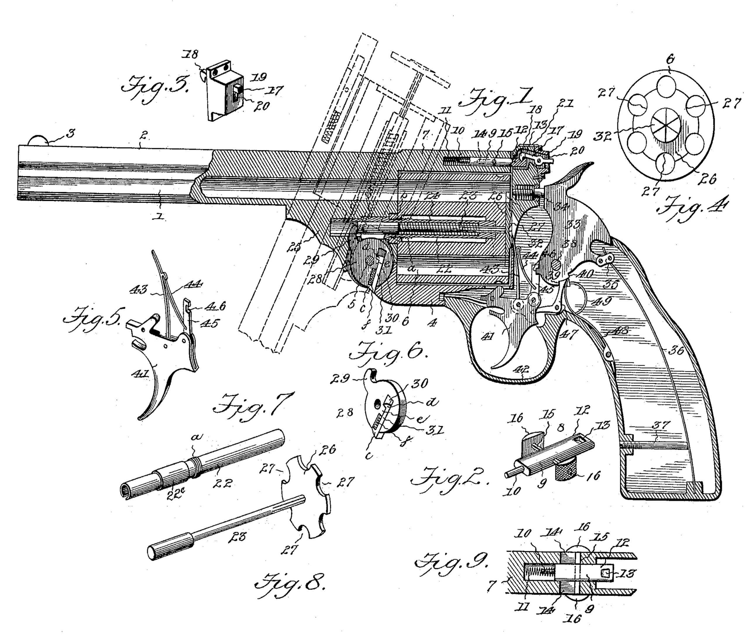
Figure 1 is a longitudinal sectional view of a revolver constructed in accordance with this invention, the dotted lines showing the barrel turned down and the operation of the extractor. Fig. 2 is a detail perspective view of the barrel-catch. Fig. 3 is a detail perspective view of the block carrying the latch which cooperates with the barrel-catch. Fig. 4 is a rear view of the cylinder and shell-extractor. Fig. 5 is a perspective view of the trigger, hammer-lifting pawl, and hand. Fig. 6 is a perspective view of the lifting-lever for operating the extractor and its retaining-dog. Fig. 7 is a detail view of the post upon which the cylinder is mounted. Fig. 8 is a detail view of the extractor rod or stem. Fig. 9 is a detail section of the barrel-strap, catch, and adjunctive parts.
Corresponding and like parts are referred to in the following description and indicated in the several views of the drawings by the same reference characters.
The numeral 1 designates a barrel of any preferred form of construction, having extending longitudinally along the top thereof a rib 2, carrying a sight 3 at the front end. The barrel 1 is connected to the frame 4 by a hinge-joint 5, which is of the usual construction in such devices, and supported by the barrel-section is a revolving cylinder 6,which receives the cartridges in a well-known manner. In the barrel-strap 7, over the top of the cylinder 6, is a barrel-catch 8, consisting of a bolt 9, with a reduced stem 10, encircled by a coiled spring 11. A tongue 12 extends rearwardly from the bolt 9 and has a recess 13 in the top near its rear end, and about mid-way the ends of the catch is a cross-arm 15, which extends through a slot formed in the barrel-strap and is provided with milled lugs 16 at its extremities, which come upon opposite sides of the strap 7 and are adapted to be engaged by the fingers of the hand when operating the catch 8. The cross-arm 15 moves in a slot 14, extending transversely through the strap 7. In the rear of the catch 8 is a latch 17, having a hook 18 at its front end to enter the recess 13 and secure the barrel in its firing position. The said latch is mounted in a block 19, secured to the standing breech in the rear of the barrel-strap 7, and is pivoted in a slot 20 and has its rear end projecting beyond the said barrel-strap for engagement by the thumb of the operator. On the top of the standing breech is a sight 21, which alines with the sight 3 on the front end of the rib 2.
The catch 8, latch 17, and the adjunctive and cooperating devices are intended to lock and release the barrel-section from the frame of the revolver.
When the cross-arm 15 is at the limit of its rearward movement in the slot 14, the latch 17 is interlocked with the catch 8, and to release the barrel it is first necessary to press down upon the projecting end of the latch 17, thereby liberating the catch 8, which is moved forward by gripping the lugs 16, after which the barrel can be turned down, as shown by the dotted lines in Fig. 1.
The cylinder 6 is mounted on a tubular post 22, secured at its front end, which has an enlarged portion 22c in a pendent portion 25 of the barrel and inclosing a spring 24, confined between the front portion of the extractor-rod 23 and the rear end of the post. A threaded shoulder a is provided about midway of the post, and the cylinder has the front end of its bore correspondingly threaded at b to pass by the threaded shoulder a and retain the cylinder in place upon the post when the barrel is turned down. The cylinder can be removed by turning the barrel down and grasping and rotating the cylinder backward until its threaded part b clears the threaded shoulder a. An extractor 26 is secured to the rear end of the rod or stem 23 and fits snugly within a depression in the rear end of the cylinder and has notches 27 corresponding in position and size with the chambers of the cylinder. The ratchet-teeth or shoulders 32, which cooperate with the hand 43, are formed on the rear face of the extractor.
A disk 28 is mounted on the pin upon which the barrel turns and has a projection 29, which enters a slot in the front end of the post 22 and extends across the path of the rod 23, so as to move the latter and the extractor when turning down the barrel. A groove or channel 30 is formed in one face of the disk 28 and receives a sliding dog 31. This dog is of less width than the groove 30 and has extensions c and d at its ends, the outer extension c being beveled on its exposed end to be engaged by the lower end of the part 25 to release the dog from the front end of the frame 4, thereby permitting the disk and the extractor to return to a normal position. The inner extension d engages with a stop e, projecting from a side of the groove 30, and limits the outward movement of the dog. A spring f is interposed between the stop e and the extension c and serves to normally hold the dog 31 projected, whereby the extension c is caused to engage with the front end of the frame 4 and hold the disk 28 stationary while turning the barrel, whereby the ejector is actuated and removes the empty shells from the cylinder. Just prior to the barrel reaching the limit of its downward movement the lower rear end of the pendent portion 25 engages with the beveled end of the extension c and presses the dog 31 inward, thereby liberating the disk and the ejector and permitting the latter to return to a normal position by the action of the spring 24 regaining itself, as will be readily understood.
The lock comprises a hammer 33, coacting with a firing-pin 34, and at the rear of the hammer is connected a stirrup 85, to which is attached the main spring 36, engaged and controlled by a lower strain-screw 37. The said hammer 33 is pivoted at 38, and in rear and slightly below its pivotal point are two sear-notches 39 and 40. A trigger 41 is located under the hammer and inclosed by a guard 42. To said trigger is movably attached a hand 43, which operates the cylinder 6 and is engaged by a spring 44 to maintain the contact of the hand with the ratchet teeth or shoulders 32, whereby a synchronous action of the hammer, cylinder, and extractor is secured. Also connected to the trigger is a hammer-lifting pawl 45, having a rear notch 46 in its upper end to engage a projection on the lower part of the hammer. A sear 47 has the front end of its horizontal arm entering a recess in the heel of the trigger to be operated, whereby when pressing upon the trigger the upper end of the vertical arm of the sear engages either one or the other of the sear notches 39 and 40. Bearing against the sear is a spring 48, and also in engagement with the lower portion of the hammer is a rebounding-spring 49, forming a part of the spring 48. Said trigger at the front is also provided with a spring 50 for well-known purposes, as also has the firing-pin 34.
In operation when the hammer is drawn backwardly a resistance of course is offered by the main spring 36, and the sear 47 and rebounding-spring 49 ride over the lower rear portion of the hammer, and when the trigger 41 is operated to release the hammer it is caused to rebound from the firing-pin by the said rebounding-spring and is caught by the sear and set half-cocked. When the hammer is thrown backward by the rebound or otherwise, the firing-pin is moved rearward by its spring and is normally out of contact with the cartridges, thereby avoiding accidents from a cartridge being exploded by striking the hammer involuntarily against an obstruction, as is frequently the case when the firing-pin bears against a cartridge.
Having thus described the invention, what is claimed as new is–
1. In a revolver or gun, the combination of a barrel movably attached to a frame, a spring actuated barrel-catch having a rearwardly-projecting recessed tongue, and a latch in rear of said tongue to engage the latter, and provided with an extended end for releasing the bolt, substantially as and for the purpose specified.
2. In a revolver or gun, the combination of a spring-actuated barrel-catch, and a latch to engage the same and having a rearwardly-projecting end and means for operating the catch and locking the parts, substantially as and for the purpose specified.
3. In a revolver or gun, the combination of a barrel hinged to a frame, a spring-actuated catch carried in the barrel-strap and having a rearwardly-projecting tongue with a recess therein, a cross-arm attached to said catch and provided with lugs at its outer ends, a block in rear of said tongue, and a latch movably mounted in said block and having a rearwardly-projecting end, substantially as and for the purpose specified.
4. In a revolver, the combination of a frame, a barrel hinged to the frame, means for securing the barrel to the frame in a firing position, a shell-extractor, a disk mounted concentric with the hinge-joint of the barrel with the frame and adapted to actuate the shell-extractor, and having a groove in one face in the rear of the pivotal connection of the disk with the frame, and having a stop extending into the groove from the front wall thereof, a dog slidably mounted in the aforesaid groove and having end extensions, the inner extension engaging with the aforesaid stop to limit the outward movement of the dog and the outer extension projecting beyond the disk and beveled on its outer end, and a spring interposed between the stop and the outer extension, substantially as and for the purpose specified.
In testimony whereof I have signed this specification in the presence of two subscribing witnesses.
PERCY WAREHAM.
Witnesses:
W. F. MOROUS,
C. J. WAREHAM.