
US 573736
UNITED STATES PATENT OFFICE.
DANIEL B. WESSON AND JOSEPH H. WESSON, OF SPRINGFIELD, MASSACHUSETTS.
SAFETY DEVICE FOR REVOLVERS.
SPECIFICATION forming part of Letters Patent No. 573,736, dated December 22, 1896.
Application filed April 6, 1896. Serial No. 586,389, (No model.)
To all whom it may concern:
Be it known that we, DANIEL B. WESSON and JOSEPH H. WESSON, citizens of the United States, residing at Springfield, in the county of Hampden and State of Massachusetts, have invented new and useful Improvements in Revolvers, of which the following is a specification.
This invention relates to revolving firearms having a cylinder which is adapted to be swung outwardly to one side of the frame of the arm for the purpose of ejecting cartridge-shells therefrom, and to provide for reloading the same, the object being to improve certain details of construction in firearms of said class whereby the manipulation thereof is facilitated, and improved safety devices are provided against the discharge of the arm inadvertently when the cylinder is not in proper position for firing; and the invention consists in the peculiar construction and arrangement of said devices, all as hereinafter fully described, and more particularly pointed out in the claims.
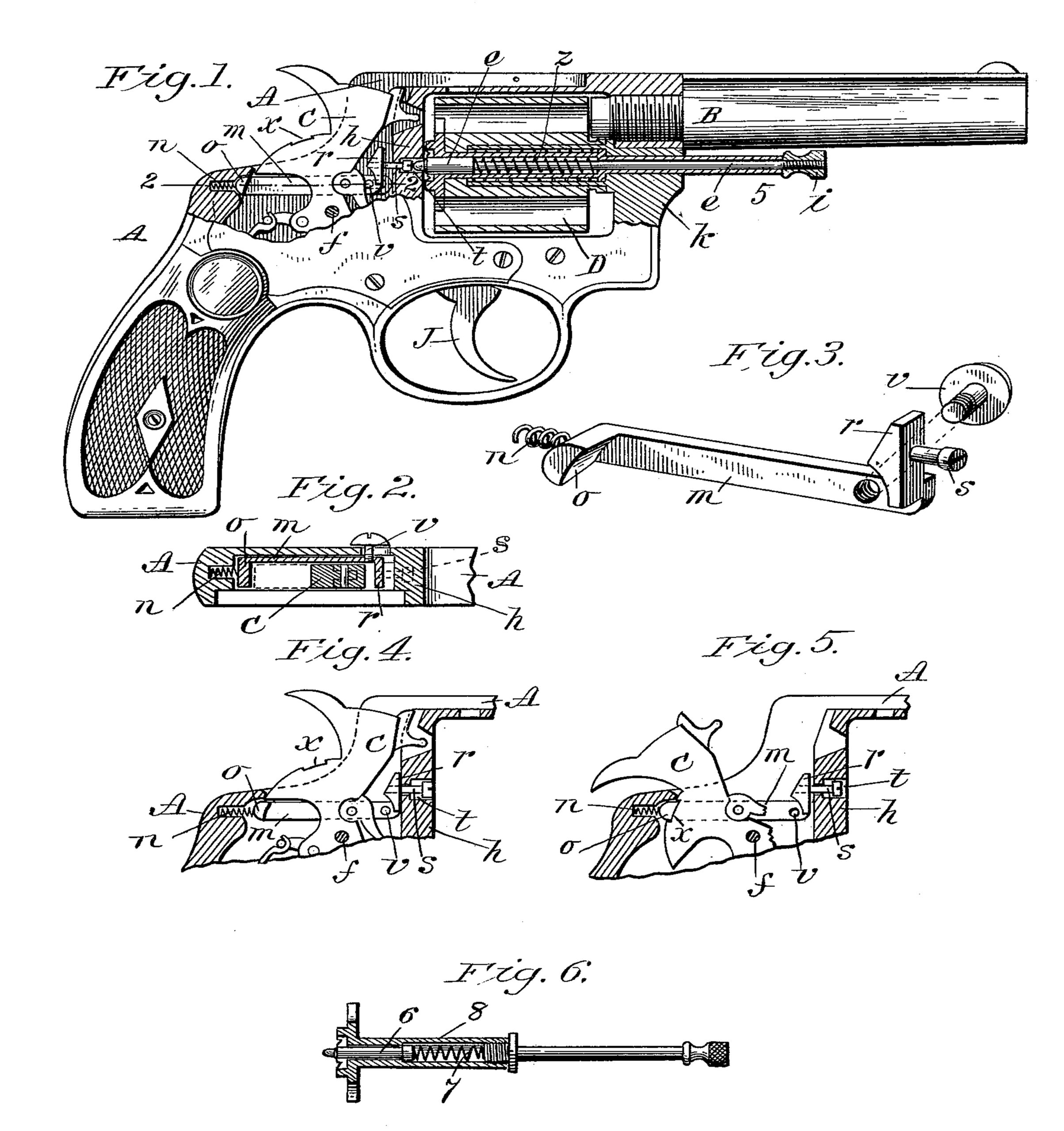
In the drawings forming part of this specification, Figure 1 is a side elevation, partly in section, of a revolver embodying our improvements, the side plate of the arm being partly broken away to disclose parts thereunder. Fig. 2 is a section of parts of the arm on line 2 2, Fig. 1. Fig. 3 is a perspective view, much enlarged, of parts of the safety devices of the arm, below described. Fig. 4 is a side view, partly in section, of a portion of the frame of the arm and of the hammer and contiguous parts, hereinafter described. Fig. 5 is a similar view to Fig. 4, but showing the hammer cocked. Fig. 6 illustrates a modified construction of the extractor mechanism and the cylinder-retaining pin, hereinafter described.
In the drawings, A indicates the frame of the arm, B the barrel, and C the hammer thereof, the latter being actuated to strike a cartridge in the cylinder D by a suitable mainspring in the usual manner. The trigger J operates in the usual manner relative to the said hammer, and the latter is pivoted at / to the frame A, as usual, and is provided with a recess x in its upper edge, for a purpose below described. The said cylinder D is supported on a yoke, substantially as shown and described in Letters Patent granted to Daniel B. Wesson, numbered 517,152, and dated March 27, 1894, whereby it is adapted to be swung outward or laterally beyond one side of said frame A, so that cartridges may be inserted into the chambers thereof and empty shells be ejected therefrom after firing. The cylinder is held in firing position within said frame, as shown in Fig. 1, by a spring-actuated center-pin or support e, its actuating-spring z serving to maintain the rear end of said pin normally in engagement in a socket t in the center of the recoil-plate h of the said frame A. Said center-pin e extends from under the barrel B through a tubular part 5 of the ejector devices of the arm, as shown. By grasping the head i of said center-pin it may be drawn forwardly and its rear end be withdrawn from its engaging socket t in said recoil-plate, thus freeing the cylinder and permitting it and its supporting-yoke, shown in said patent, to swing laterally, as and for the purpose aforesaid. Upon swinging the cylinder back into the arm preparatory to firing the same the rear end of said pin will become automatically engaged in said recoil-plate socket, provided the cylinder be brought fully to the proper firing position. It may, however, occur, through inadvertence or by reason of carelessness in not properly cleaning the arm, that the cylinder is not carried far enough into the arm to permit the end of said pin e to become entered into said recoil-plate socket, whereby the cylinder is locked in firing position, and therefore the arm should not, under such circumstances, be fired. To render such inadvertent firing action impossible and to provide other features of safety construction and convenience in arms of this class, the below-described improvements are provided.
A safety bolt or catch m is applied between one side of the hammer C and the adjoining inner side of the frame A, as illustrated in the drawings, and there properly supported for longitudinal movement, preferably by inserting its body portion in a groove in said frame. Said bolt, as shown in Fig. 3, has a laterally-extending hammer-engaging arm o on its rear end and a head r on its opposite end. A pin s, preferably a screw, is provided on said head r, which extends from the rear into the said socket t in the recoil-plate, directly in line with said center-pin e, when the rear end of the latter is entered into said socket. A thumb-bolt or knob v is screwed to the side of said bolt through a slot in said frame, and when in place therein the head thereof lies against the outer side of said frame in convenient position for manipulating the same to slide said bolt with the thumb of the right hand when the pistol is held in the latter. A spring n, at the rear end of said bolt m, serves to move the same forwardly to the positions shown in Figs. 4 and 5. The hammer C has a safety-recess x or any suitable abutment thereon for engagement with the said arm o of bolt m when the hammer is cocked, as shown in Fig. 5, and when the cylinder D is in a position in the arm swung entirely or partially out of the frame thereof it is not in a safe firing position, and said bolt, actuated by said spring n, takes the position shown in Fig. 4, wherein said arm o is brought under the tail of the hammer and the latter is so locked that it cannot be cocked because said center-pin is not in place. When, therefore, said cylinder is in the arm in firing position, the said center-pin e is driven by its spring z against said pin s in the said socket in the recoil-plate h, and thereby the bolt m is driven rearwardly to the position shown in Fig. 1, thus permitting the hammer to be freely operated for firing the arm in the usual manner. Said center-pin e, when the cylinder and hammer are in the positions shown in Fig. 1, may be pushed forward by pressing the thumb against the head of said thumb-bolt v, thereby permitting the cylinder to be thrown outwardly to be loaded or for ejecting cartridges therefrom. Should it occur that the hammer be cocked before swinging the cylinder nearly to firing position in the frame, thus preventing the end of said pin e from engaging in said recoil-plate socket, the bolt m will automatically take the position shown in Fig. 5, engaging its arm o in said notch x in the rear edge of the hammer, and thus prevent the usual operation of the hammer for firing the arm; but the moment the cylinder is in place centrally the extremity of said pin e enters said socket, striking the end of the pin t, and drives bolt m backwardly and disengages it from the hammer, so that the arm may be fired.
The modified construction shown in Fig. 6 provides a short center-pin 6 in the end of the ejector-tube 7. A spring 8 in said tube 7, behind said pin 6, holds it normally in position to engage with said socket t in the recoil-plate, as in the case of the center-pin e, and permits it to recede under the action of the forward movement of said bolt m when the latter is actuated by pressing the thumb| against the head of said bolt v; but said pin 6 cannot be otherwise disengaged from said recoil-plate.
Having thus described our invention, what we claim, and desire to secure by Letters Patent, is—
1. In a revolver, and in combination with the cylinder-support thereof, the hammer, mainspring, and trigger, and a hammer-catch in position to engage said hammer and hold it against firing, said hammer-catch being in position to be thrown out of such engagement with the hammer and rendered inert by the cylinder-support when the latter is in position for the proper firing of the weapon, all combined substantially as described.
2. In a revolver, the cylinder and its supporting-piece, the hammer and a spring-actuated catch therefor, and a projection from the cylinder-support impelled by a spring of superior power to that of the hammer-catch, and in position to disengage the same from the hammer when the cylinder is in firing position, all combined substantially as described.
3. In a revolver, the frame, barrel, and cylinder, the supporting-pin of the cylinder and a spring pressing the said pin into a socket in the frame when the cylinder is in firing position, a sliding bolt in the frame and a spring bearing the same into locking engagement with the hammer, said supporting-pin having such relation to the sliding bolt as to disengage the same from the hammer when the cylinder-pin is in normal closed position, all combined substantially as described.
4. In a revolver of the class described, the recoil-plate having a centrally-located socket therethrough, and a center-pin in said cylinder automatically engaging in said socket, combined with the hammer, a bolt within the frame of the arm having a pin thereon entering the rear end of said socket for engagement with said center-pin, and an arm thereon for engagement with the tail of the hammer, and a spring moving said bolt toward said center-pin, substantially as set forth.
5. In a revolver of the class described, the recoil-plate having a centrally-located socket therethrough, and a center-pin in said cylinder automatically engaging in said socket, combined with the hammer having a recess; in its border, a bolt within the frame of the arm having a pin thereon entering the rear end of said socket for engagement with said center-pin, and an arm thereon for engagement with said recess in said hammer, and a spring moving said bolt toward said centerpin, substantially as set forth.
DANIEL B. WESSON,
JOSEPH H. WESSON.
Witnesses:
H. A. CHAPIN,
K. I. CLEMONS.