
US 611826
UNITED STATES PATENT OFFICE.
DANIEL B. WESSON AND JOSEPH H. WESSON, OF SPRINGFIELD, MASSACHUSETTS.
CYLINDER-STOP FOR REVOLVING FIREARMS.
SPECIFICATION forming part of Letters Patent No. 611,826, dated October 4, 1898.
Application filed August 7, 1897. Serial No. 647,490. (No model.)
To all whom it may concern:
Be it known that we, DANIEL B. WESSON and JOSEPH H. WESSON, citizens of the United States of America, residing at Springfield, in the county of Hampden and State of Massachusetts, have invented new and useful Improvements in Cylinder-Stops for Revolving Firearms, of which the following is a specification.
This invention relates to revolving firearms, and has for its object the provision of improved cylinder-stop devices therefor; and the invention consists in the peculiar construction of said stop and cooperating parts of the arm, all as hereinafter fully described, and more particularly pointed out in the claims.
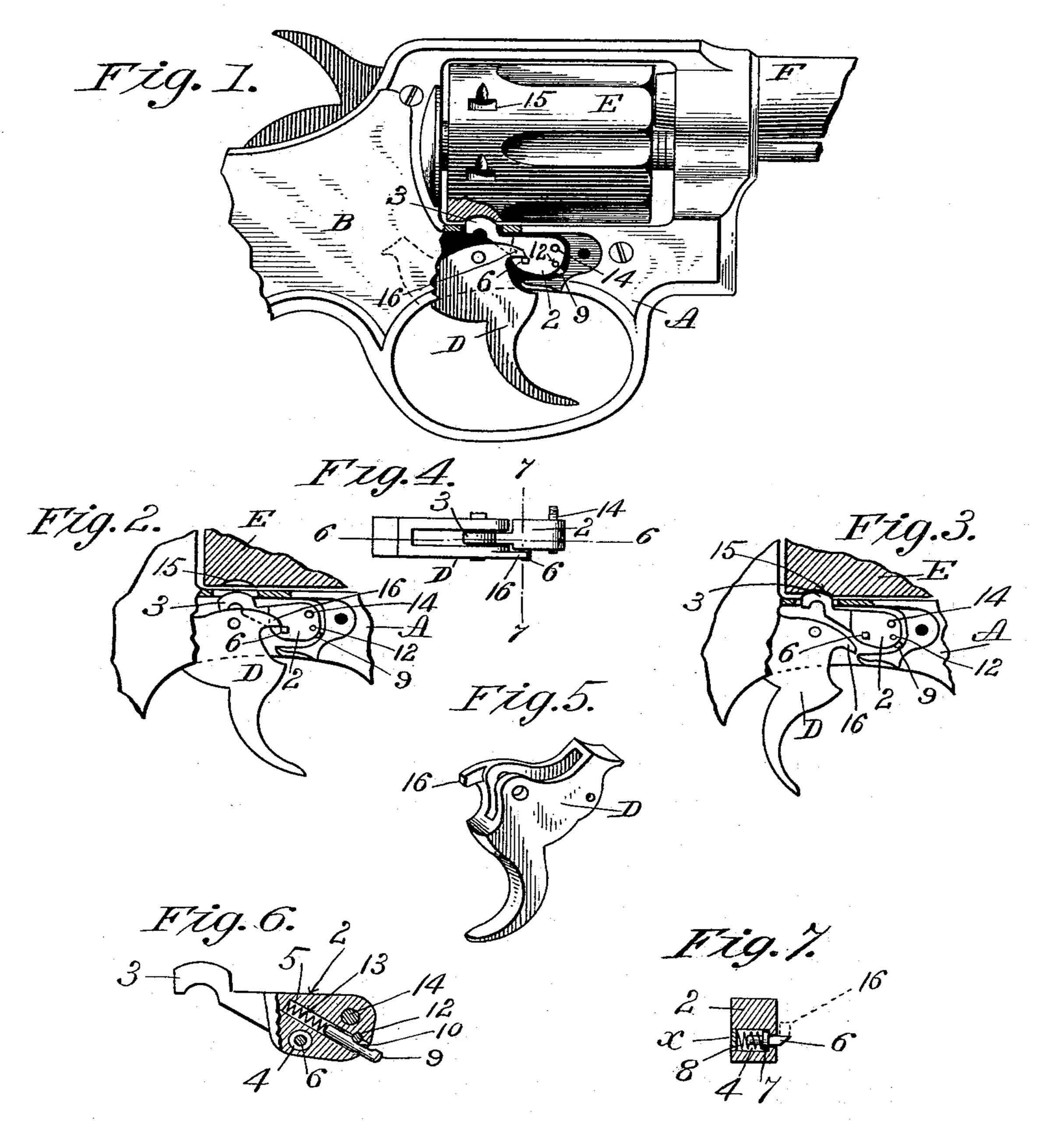
In the drawings forming part of this specification, Figure 1 is a side elevation of the cylinder-containing portion of a revolving firearm having our cylinder-stop improvements applied thereto, said figure showing a part of the lock-plate over said stop and the trigger broken away. Fig. 2 is a side view of a part of the trigger, the cylinder-stop and parts of the cylinder, and frame of the arm contiguous to said trigger, as hereinafter described. Fig. 3 is a similar view to Fig. 2, but showing the trigger and cylinder-stop in different relative positions. Fig. 4 is a top edge view of the trigger and cylinder-stop. Fig. 5 is a perspective view of the trigger, looking at its upper side. Fig. 6 is an enlarged side elevation of the cylinder-stop, partly in section, on line 6 6, Fig. 4. Fig. 7 is a section of the cylinder-stop on line 7 7, Fig. 4.
Referring to the drawings, 2 is the cylinder-stop, which is adapted for intermittent engagement with the cylinder E, as below described, and it consists of a metal body and an integral cylinder-engaging neck 3. In the body of said cylinder-stop are formed two recesses 4 and 5. Said recess 4 has a movable trigger-catch 6 therein, on which is a shoulder 7 to limit its motion in one direction. A spring S in said recess 4 engages by one end the shoulder of said trigger-catch 6, and its opposite end abuts against the inner side of a plug x, by which one end of said recess is closed. Thus the outer end of said trigger-catch 6, which is slightly beveled, as shown in Fig. 7, is held by said spring S normally in the position there shown— that is, with its beveled end projecting more or less beyond the outer side of the cylinder-stop and adapted to be moved inwardly by the engagement of a part of the trigger D therewith, as below described, and to be again thrown outwardly by the action of said spring. The other recess 5 in the body of said cylinder-stop 2 receives a spring-actuated plunger-pin 9, (see Fig. 6,) which preferably has a convex outer end and a shallow recess 10 in one side thereof. A pin 12 extends through the side of the said cylinder-stop in such position as to cause it to enter said recess 10, as shown, and hold the pin 12 from sliding quite out from said recess 5, but allowing said plunger-pin 9 a certain degree of endwise motion for the purpose below described. A spring 13 is inserted in said recess 5 between the base of the latter and the inner end of said plunger-pin 9, which serves to drive the latter outwardly. The said cylinder-stop is hung for a swinging motion on the inner wall of the frame of the arm under the cylinder upon a pin 14, which is screwed by one end into a socket in said wall. The positions of said pin and stop in the arm are indicated in Figs. 1, 2, and 3. The outer end of said pin is preferably supported in a socket on the inside of that part of the lock-plate which covers the trigger and said stop. Said pin 14 constitutes a support for said cylinder-stop, whereby provision is made for a vibratory movement of said neck 3 under the cylinder E. Said cylinder is provided with the usual stop notches or recesses 15, and that part of the frame A directly under said cylinder is perforated, as shown, to permit said stop-neck 3 to swing freely toward and from said cylinder and to enter said stop notches one after the other, whereby the cylinder has its cartridge-chambers held in line with the bore of the barrel F of the arm, as usual. It will be noted that the cylinder-stop 2, including said several connected parts thereof, is handled as one piece in putting it into or removing it from the arm. Consequently the work of assembling the cylinder-stop parts and of removing and replacing them in cleaning the revolver is greatly simplified as compared with stop constructions heretofore in use, and strength and durability of parts are secured and loss of parts is prevented. When the cylinder-stop 2 is in operative position in the arm, as shown in Fig. 1 and elsewhere, the outer end of said plunger-pin 9 has a bearing against the adjoining curved-shaped portion of the recess-wall in the frame A, in which said stop operates. It will be seen that the pressure of the end of said plunger-pin 9 against said adjoining recess-wall in the frame A, driven by said spring 13, tends to swing the cylinder-stop 2 from the position shown in Fig. 2 to that which causes the engagement of the neck 3 thereof with the cylinder E, as in Fig. 3, which is the normal position of said cylinder-stop. Said trigger D is provided with a stop-engaging projection 16, whose extremity is in proximity to said cylinder-stop and is adapted to engage with the projecting end of said trigger-catch 6 when the trigger D is pulled, as in the act of revolving the cylinder to bring a cartridge to firing position behind the barrel F. Thus the said neck 3 of the cylinder-stop 2 is swung downward and out of engagement with the cylinder E, as in Fig. 2, thereby permitting the ratchet-and-pawl devices of the arm, which as usually constructed are operated
by the trigger, to freely turn the cylinder E, for the purpose aforesaid; but immediately that the cylinder E shall have been so turned said trigger projection 16 slips off said trigger-catch and passes below it, as shown in Fig. 3. Said plunger-pin 9 is now, through its said spring 8, forced outwardly, causing the said neck 3 of the cylinder-stop 2 to swing upwardly against the cylinder E and to become engaged with the next succeeding stop-notch 15 therein, thereby firmly holding the cylinder E in position while a cartridge shall be fired. Upon releasing the trigger D its usual actuating-spring will swing it back to its normal position, (shown in Fig. 1,) and in so doing said projection 16, moving upwardly, strikes the said beveled under side of said catch-pin 6 and, moving the latter inwardly, passes by and above it, and said last-named pin then springs outwardly again under said projection to the position it occupied before the trigger D was pulled and as shown in said last-named figure.
The within-described improved cylinder-stop devices located under the cylinder provide for leaving that part of the frame of the arm which extends between the hammer and the barrel F and over the cylinder E quite free from any projections, which in some previous constructions have been found objectionable.
Having thus described our invention, what we claim, and desire to secure by Letters Patent, is——
1. In a revolver, the notched cylinder, the cylinder-stop pivoted in the frame in position to engage the cylinder-notches, and the spring-pin carried in a recess in said cylinder-stop and having an end projecting against a curved bearing-surface in the frame, in combination substantially as described.
2. In a revolver, the notched cylinder, the cylinder-stop pivoted in the frame in position to engage the notched cylinder as usual, a spring-pressed pin carried by the cylinder-stop and engaging a curved bearing-surface in the frame, the spring-pin projecting from the side of said cylinder-stop and having a beveled end, and the trigger having a projection engaging said side pin when moving in one direction, all combined substantially as described.
DANIEL B. WESSON,
JOSEPH H. WESSON.
Witnesses:
H. A. CHAPIN,
K. I. CLEMONS.