
US 427833
UNITED STATES PATENT OFFICE.
HOMER M. CALDWELL, OF WORCESTER, MASSACHUSETTS, ASSIGNOR TO THE HARRINGTON & RICHARDSON ARMS COMPANY, OF SAME PLACE.
FIRE-ARM.
SPECIFICATION forming part of Letters Patent No. 427,833, dated May 13, 1890.
Application filed February 15, 1890. Serial No. 340,505. (No model.)
To all whom it may concern:
Be it known that I, HOMER M. CALDWELL, a citizen of the United States, residing at Worcester, in the county of Worcester and State of Massachusetts, have invented certain new and useful Improvements in Fire-Arms, of which the following, together with the accompanying drawings, is a specification sufficiently full, clear, and exact to enable persons skilled in the art to which this invention appertains to make and use the same.
My present invention relates to the construction of the cylinder stop-bolt and its accompanying mechanism, and to the combination thereof with the trigger; also, to the peculiar construction and arrangement of means for intercepting and detaining the stop-bolt at the initial movement of the trigger for disengaging the cylinder to permit the rotation thereof, and for later throwing off the detaining-latch as the trigger swings backward to permit the stop-bolt to again engage with the cylinder at the proper instant in the action, the object being to provide an efficient, convenient, and desirable mechanism for the purpose specified.
The particular subject-matter claimed is hereinafter definitely set forth.
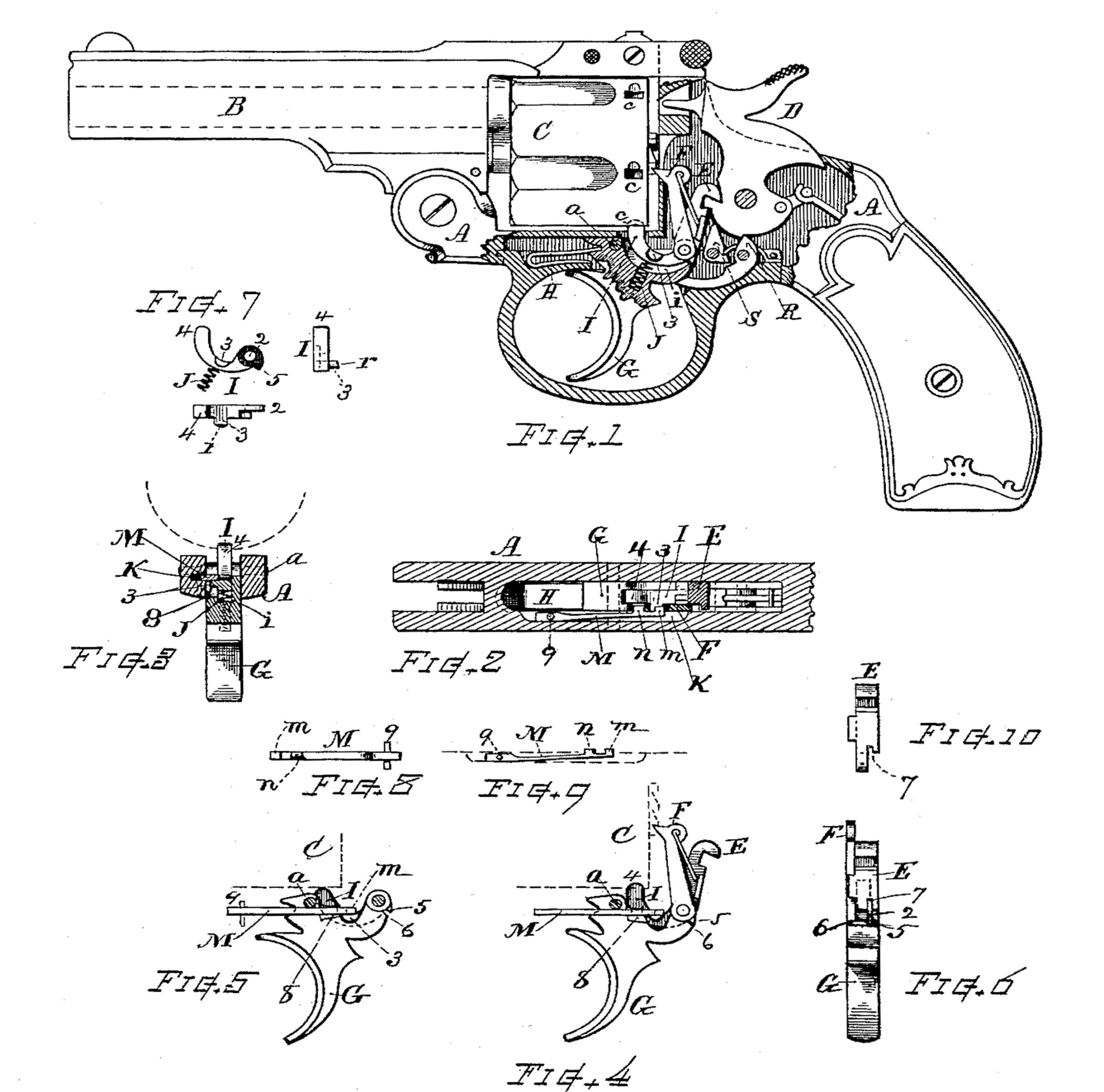
In the drawings, Figure 1 is a view of a revolver embracing my invention, some parts being shown in section the better to illustrate the details of construction. Fig. 2 is a horizontal section through the lower part of the action, showing the location of the cylinder stop-bolt and its detaining device in relation to the frame and other parts of the action. Fig. 3 is a vertical transverse section through the stop-bolt, retaining-latch, and frame at the rear part of the trigger. Fig. 4 is a side view of the trigger, the lifter, cylinder-actuating pawl, stop-bolt, and detaining-latch separate from the frame. Fig. 5 is a side view of the trigger, stop-bolt, and latch as at positions when the trigger is slightly drawn backward. Fig. 6 is a view of the trigger and parts connected therewith, showing the hinging-joint from the rear side thereof. Fig. 7 shows in detail the stop-bolt separate from the action. Figs. 8 and 9 show the details of the retaining-catch; and Fig. 10 is a rear view of the hammer-lifter separate from other parts.
Referring to parts, A denotes the frame; B, the barrel; C, the cylinder; D, the hammer; E, the hammer-lifter; F, the pawl or hand that engages with the ratchet for rotating the cylinder; G, the trigger, and H the trigger-spring. These named parts are arranged for action substantially as set forth in my previous application for Letters Patent, or in any suitable or well-known manner.
In accordance with my present invention, the trigger G, which is fulcrumed or pivoted at a, has a recess i in its top part for the reception of the cylinder stop-bolt I, which is hinged to the top part of the trigger, preferably on the same hinging-axis with the hammer-lifter E and hand F, and arranged to swing up and down in relation to said recess. This stop-bolt I is best formed, as shown in Fig. 7, with a hinging-eye 2 at one end, a curved body having a laterally-projecting lug 3 on the side thereof, and a rounded end 4 for engagement with the notch or recess c in the peripheral surface of the cylinder. Said stop-bolt is disposed in relation to the trigger and cylinder in such manner that its front end 4, which projects up through a recess in the frame, can engage the notch c when the trigger is at any position in its range of movement, except the stop-bolt be depressed, as will be hereinafter explained.
A depression is formed in one side of the trigger-top to accommodate the lug 3 when the stop-bolt is depressed into the recess i, and a spring J is provided between the stop- bolt and trigger for sustaining said stop-bolt normally with its fore end elevated from the trigger. Said spring is in the present instance a small coiled wire confined in a hole drilled into the body of the trigger from the bottom of the recess i, as indicated in Figs. l and 3.
A projecting lug or shoulder 5 on the hinge portion of the stop-bolt engages with a shoulder 6 on the trigger and serves to limit the range of movement of said stop-bolt and prevent the spring J from forcing the stop-bolt too far upward at any time.
The hinging end of the hammer-lifter E is best fitted with a recess 7 to swing over the lug 5. (See Figs. 6 and 10.)
The notches c in the cylinder-surface are respectively made so as to embrace the end 4 of the stop-bolt at both sides, so that when in engagement said bolt prevents rotation in either direction. The entering side of the recess is slightly cut away to insure the stop-bolt entering the notch, or so that the cylinder cannot throw past its position by quick movement.
M indicates a spring-bar or detaining-latch, having a lug or portion m, that catches over the stop-bolt I or projection 3 for intercepting it at the initial movement of the trigger. Said latch or bar is provided with a second lug n, that engages with a cam or beveled surface 8 on the side of the trigger G for retracting the latch when the trigger is drawn backward to a sufficient extent. This latch is best arranged within a longitudinally-disposed groove K, formed within the inner side of the frame laterally from the mortise or chamber within which the trigger G and guard L are assembled, said latch being retained at one end by means of a pin 9, that passes upward through the frame, or in other efficient manner, while its opposite end m is by reason of the springing action caused to protrude from the groove sand engage the stop-bolt I, as indicated in Fig. 2.
The end surfaces on the lug 3 of the stop-bolt and the lug m of the latch are preferably made slightly inclined, as shown at r, Fig. 7 so that the contact of said inclined surfaces will effect a retardation of the upward movement of the stop-bolt after the lug m has slipped from the top surface of the lug 3. This is for the purpose of holding the stop-bolt until the cylinder has made its desired revolution and after the beveled surfaces on the trigger and spring-bar have exhausted their limit of action.
In the operation when the trigger is at forward position the stop-bolt is in engagement with the notch c of the cylinder and the latch-lug m is over the lug 3, as in Figs. 3 and. 4. When the trigger is drawn back, the first part of its movement raises the hinging-axis of the stop-bolt I, while the central portion thereof is held at a stationary position by the overlying lug m of the latch M. Consequently the front end of the stop-bolt is depressed and the cylinder is released to be rotated by the pawl F. As the trigger is pulled farther backward, the movement causes the beveled surface 8 by action against the lug n to force the latch back into its groove K until the end of lug m releases the stop-bolt. Then the spring J immediately lifts the end of the stop-bolt into contact with the cylinder, so that it will engage with a notch c whenever such notch is brought into corresponding position with the stop-bolt.
By the construction shown and described I produce a very efficient and desirable stop-bolt mechanism, and one which is particularly well adapted for double-action revolvers.
Another advantage of this construction is that it greatly facilitates the assembling of the parts, because the stop-bolt I and spring J can be put together before the trigger is inserted in the frame, and the latch or spring M, being in one side of the frame, is out of the way, so that the guard, the trigger, and the trigger-spring can be assembled or entered without interfering in any manner.
The rebounder R and the sear S can be arranged as described in my former application for Letters Patent, or in such suitable manner as may be desired.
I am aware that in a previous patent there is shown and described a revolver mechanism wherein the stop-bolt is fulcrumed upon the trigger-hinging pivot, and its front end fitted with a hook that is engaged by means of a bolt, which is fitted within and projects forward from the trigger for pulling down said stop-bolt when the trigger is pulled. It will therefore be understood that I do not wish to embrace such mechanism as within the scope of my claims.
I claim as my invention herein to be secured by Letters Patent—
1. The stop-bolt pivoted to the movable rear part of the trigger and having a movable end that extends up through the frame, and a spring disposed between said stop-bolt and the trigger in combination with the cylinder and trigger, and a retractable detaining-latch, for the purpose set forth.
2. A stop-bolt hinged to the movable rear part of the trigger and adapted for engaging a recess in the cylinder, and a latch or detaining-lug that normally engages with and resists movement of said stop-bolt at the initial movement of the trigger, in combination with the revolver-cylinder, and the trigger provided on its side with a cam or incline that retracts said detaining-lug and releases the stop-bolt as the trigger moves backward.
3. The combination, with the cylinder and cylinder-rotating devices, of a stop-bolt hinged to the trigger at the lifter-axis, a spring for maintaining said stop-bolt elevated, a spring-latch fixed in the side of the frame, having a lug that engages and detains said stop-bolt, and oppositely-beveled surfaces on the spring latch and on the trigger, which coact for discharging said latching-lug and releasing the stop-belt as the trigger is drawn backward, substantially as set forth.
4. In combination with the cylinder and the trigger, the stop-bolt and stop-bolt-latching spring, with the engaging-lugs on said stop-bolt and latching-spring having their end surfaces slightly beveled, as described, whereby said stop-bolt is detained in depressed position by the friction of said end surfaces until the faces of the engaging-lugs pass each other and the cylinder has made the desired degree of movement.
5. The frame provided with a lateral longitudinal groove or slot extending outward from the guard-mortise and the spring-latch for holding the stop-bolt disposed in said slot, in combination with the trigger, the stop-bolt hinged thereto, and the guard, substantially as set forth, whereby said spring is supported without interfering with the trigger-spring and fore-end of the trigger.
6. The stop-bolt hinged to the top of the trigger at the lifter-axis and having the projection or lug 5 on the hinging-eye, the trigger provided with the recess i and the shoulder 6, and the stop-bolt spring J, in combination with the cylinder, cylinder-rotating pawl, and stop-bolt-detaining latch, substantially as set forth.
7. The combination of the stop-bolt, the cylinder-actuating pawl and hammer-lifter severally hinged to the trigger on the same axis, and the stop-bolt-engaging latch fitted in a recess in the side of the frame, in combination with the frame, the cylinder, the trigover having the cam-surface for throwing off said latch, the hammer, the rebounder, and the pivoted sear, all substantially as and for the purpose set forth.
Witness my hand this 12th day of February, A. D. 1890.
HOMER M. CALDWELL.
Witnesses:
CHAS. T. BURLEIGH,
ELLA P. BLENUS.