
US 7218
UNITED STATES PATENT OFFICE.
HANS IVERSEN, OF NEW YORK, N.Y.
IMPROVEMENT IN REVOLVING-BREECH FIRE-ARMS.
Specification forming part of Letters Patent No. 7,218, dated March 26, 1850.
To all whom it may concern:
Be it known that I, Hans Iversen, of the city of New York, gunsmith, a native of the Kingdom of Denmark, having resided more than one year next preceding the date hereof in the United States, and having duly made oath of my intention to become a citizen thereof have invented, made, and applied to use certain new and useful Improvements in the construction of what are usually known as “Repeating Fire-Arms,” for which improvements I seek Letters Patent of the United States; and I do hereby declare that the construction, operation, and effects of the said improvements are fully and substantially set forth and shown in the following description and in the drawings annexed to and making part of this my specification of my said improvements, wherein—
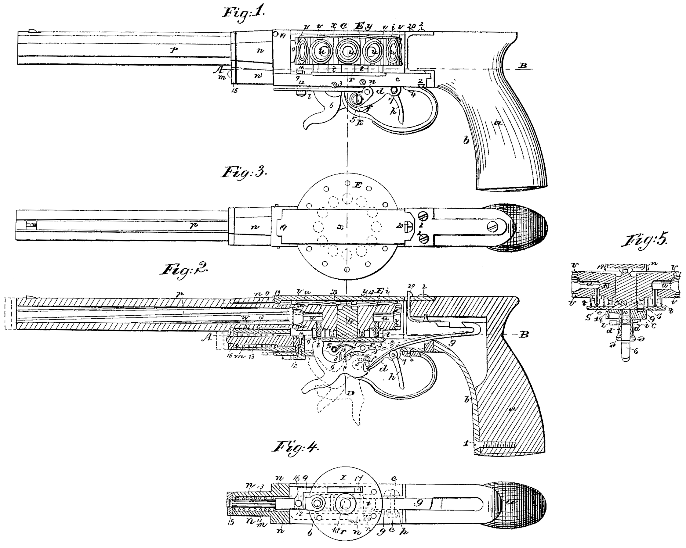
Figure 1 is a side view of a repeating-pistol having twelve discharging-chambers, shown as complete for use, with my improvements. Fig. 2 is a longitudinal section, and Fig. 3 is a plan, of the same. Fig. 4 is a plan showing the positions of the parts at the line A B of Figs. 1 and 2. Fig. 5 is a cross-section at the line C D, Figs. 1, 2, and 3; and the like letters and numbers, as marks of reference, apply to the same parts in all the several figures, as follows:
a is the stock or handle, countersunk to take the metal plate b, with a screw, 1. The forward part of this plate b is formed as a fork to pass the mainspring g. Forward and beyond the fork the metal may be either continued solid with the plate b or made in two parts connected to the plate b to form a frame, c, on which the Working parts and barrel are mounted. The frame c and plate b are united to the fore end of the stock by vertical screws 2 2.
Beneath the frame c and solid with it are two pendent flanges, d d, each with a notch at 3, to take the points of a fork cut into the fore end of the guard e, the rear end of which is screwed to the frame or cover-piece c by a screw, 4.
At 5 in the flange d is a center, carrying the hammer and tumbler 6, This is connected by a bridle, f, to the fore end of the mainspring g, the rear end of which is housed in the stock, and is fitted with a returned part having a slot to take a stud hooked toward the rear, by which the spring is held in place for work, as seen in Fig. 2.
At 7 is the center-pin to carry the trigger h, having the finger-piece within the guard, the joint made to be clear of the mainspring, and the lever part fitted on one side with a point, S, to take a toe, 9, on the rear of the sear i. This is fitted with a sear-spring, 10, and is adjusted to take the half-cock and full-cock notches on the hammer-tumbler in the usual manner.
On the left-hand side of the frame c the center 5 is fitted as a square to take an arm, k, that is fitted with a joint, 11, to carry a flat slide, l, beneath the frame c and beyond the flanges d d. This slide is expanded to the right of the instrument, with a mortise to take a stud, 12, and keeper-screw. This part may be duplicated, so as to have an arm, k, on each side. The stud 12 is pendent from the rear end of a round slide-rod, m, which has round a reduced part an expansive helical spring, 13, the rear end of which takes a stop-shoulder. The slide in and spring 13 are placed in a cylindrical hole or chamber, n’, on the lower part of the breech-block n.
The slide m and spring 13 have a shoulder in front of the spring. This cylinder n’ may be made solid with or separate from the block n. The breech-block n is secured by screws to the forward end of the frame c, and is made to surround the reduced breech part o of the barrel p, which has at the lower part of the shoulder formed by the reduction of the barrel an arm or stud, 15, that takes the forward end of the slide m by a screw joint. On the upper part of the stud 12, at the rear of the slide m, a screw, 16, holds the forward end of a spring, q, the rear of which lies in a countersink in the right of the frame c, and is finished with a latch-point, 17, acting upward through a slot in the center plate, r, which is secured by screws on the frame c, and has a center cylinder, 18, which carries a thick steel disk, E, forming the repeating part of the arm and made on the lower face with a circular-face ratchet, s, of twelve teeth, which receive and are acted on by the catch 17 on the slide q. The under face of the disk E has also twelve nipples, t. These are each surrounded by a small cylinder a little higher than the nipple. These, with the nipples, overlie the center plate, r, so that the caps cannot be shaken out by the shock of a discharge. The forward edge of the plate r has a segment gut in, to pass the hammer to the nipples, and each nipple leads to the rear of a chamber, w, in the disk E. The mouths of these chambers are expanded to receive rather more than one-half of a bullet, and round each mouth is a circular groove, v, countersunk to fit and receive the breech end of the reduced part o of the barrel p. The entrance to the interior part of this is shaped so as to fit the interior edge of each circular groove, and cup-shaped to be in contact with the bullet when discharging. The fixed breech-block n is rifled along the length in the interior surface, as at w, to cause less friction, and to permit the entrance of any dust or flash that may by any possibility be blown out between the grooves v and the entering endo of the barrel breech.
At 19 on the upper rear of the breech-block n a joint carries the fore end of a cover-plate, x, the under side of which has secured on it a two-part spring, y, the action of which is to press on the upper face of the repeater-disk E. The rear end of the spring has a stud, z, that drops into a gaged countersink on the upper face of the disk E, over each chamber u. This stud rises out as each movement commences, and at the end of the movement drops in to hold the disk in place until discharged, and at 20 a spring-catch on the fore end of the stock holds down the rear end of the cover-plate x.
When thus made and adjusted the instrument is to be used as follows: When about to load the piece the hammer 6 is to be drawn to the half-cock. This will project the slide l forward, and with it the slide n, compressing the helical springs 13 and forcing the barrel p forward, so that the rear of the part o is just clear of the disk. This position of the parts is shown in red lines in Fig. 2, and leaves the disk at liberty to be taken out and caps put on the nipples. Then the chambers u are to be successively charged with powder, which is to be kept in by bullets, that are to be of a size that will fill the mouths tightly, so as to require pressure or a slight blow to force them in, so that the disk E will rotate without the bullets touching either the breech-block 3 or the rear end of the barrel in the block. When the chambers are loaded the disk is to be secured down by the cover-plate x, when, on full-cocking the hammer, the parts Will assume the position shown by blue lines in Fig. 2, with the shoulder and arm 15 of the barrel a little farther from the breech-block and the spring 13 more strongly compressed. On pulling the trigger for a discharge the point 8 depresses the toe 9 and sear i from the tumbler, and the mainspring g throws the hammer On the nipple with a force that is accelerated by the recoil or expansion of the spring 13 through the stud 12, slide l, and arm k, which expansion is also acting to draw back the barrel and place the rear of the part o in one of the grooves v, at the instant before the hammer strikes the nipple, to explode the charge and drive out the bullet, when the parts will assume the position shown in Figs. 1 and 2. The slide l takes the shock of the balls on the barrel to the arm k, with which it is so nearly in line, as seen in Fig. 1, as to throw any shock on the center 5 without the liability to raise the hammer, which is also held down by the mainspring g. The latch-spring q has moved forward with the slides l and m, and is now returned with them, the point 17 having depressed the spring into the countersink in the frame c until the point has passed under and behind the next ratchet-tooth s, and behind sufficient to allow of moving the barrel out of the groove, which will be at the half-cock of the hammer, and on full-cocking the hammer the point 17 takes the ratchets and carries the disk E the distance between two centers of the chambers and completes the movement, so as to place the center of the next chamber in line with the axis of the barrel, ready for another discharge of the powder and bullet, the action of the parts being the same at each successive discharge and recocking of the instrument.
This invention is shown in the drawings as connected to a pistol with twelve chambers; but the instrument may be made with a less or greater number of chambers, or made smaller than shown in the drawings, or may be attached to any kind of larger instrument for the same purposes, the sizes of the parts being changed in proportion to the size of the instrument.
It will be seen by Figs. 2 and 5 that the chambers are made conical toward the center of the disk, and that the cup for the bullet has a slightly similar shape. The first effect is in creasing the metallic strength of the chambers and throwing the line of explosion more directly in the line of the centers, so as to act most on the horizontal axis of the bullet. The effect of the form before the powder is to slightly compress the bullet, as that is driven in, and thereby hold both that and the powder in place. The disk E is shown circular, but may be a polygon of as many sides as there are chambers employed.
It will be obvious that by increasing the strength of the spring 13 the mainspring g may be dispensed with, the motion and blow by the hammer being derived from the spring 13, and also that any other means may be used in place of the opening for the hammer in the plate— such as a sliding plug, the outer end to be struck by the hammer, the inner end striking the cap-such means being used to prevent the percussion-caps from falling off the nipples, these being mere practical variations.
The principal differences between this instrument and those that have preceded it are, first, that no other fire-arm within my knowledge is fitted with an arm on the tumbler-center of the hammer, which arm takes a slide to move the barrel forward out of a groove around the breech and clear of the convexity of the ball on cocking the piece, and replaces the end of the barrel again in the groove around the breech to be next discharged by the motion of the hammer and springs, as heretofore described; second, I do not know of any other fire-arm in which the motion of the barrel in sliding forward is communicated to the revolving breeches by means of a connected slide-latch and ratchet-teeth, as herein described.
I therefore claim as new and of my invention and desire to secure by Letters Patent of the United States—
1. The arrangement of the arm k, slides l and in, or their equivalents, whereby the motion of half-cocking and cocking the hammer is communicated to the barrel to open the joint formed by the grooves v around the breech u, and also to close said joint on the discharge of the piece by the operation of the hammer 6, slides land m, and spring 13, alone or in conjunction with the mainspring g, substantially as described and shown.
2. The arrangement of the slide q and circular ratchets s, or their equivalents, whereby the motion of the barrel sliding forward is made to revolve the chambers the required amount to bring the next chamber in line for the next discharge of the piece, substantially as described and shown.
In witness whereof I have hereunto set my signature this 31st day of January, 1850.
H. IVERSEN.
Witnesses:
Wm. Serrell,
Lemuel W. Serrell