
US 5316
UNITED STATES PATENT OFFICE.
L. H. GIBBS, OF OBERLIN, OHIO.
IMPROVEMENT IN FIRE-ARMS.
Specification forming part of Letters Patent No. 5,316, dated October 2, 1847.
To all whom it may concern:
Be it known that I, Lucius H. Gibbs, of Oberlin, in the county of Lorain and State of Ohio, have invented a new and Improved Repeating-Rifle; and I do hereby declare the following to be a full, clear, and exact description of the construction and operation thereof, reference being had to the accompanying drawings, making a part of this specification, in which—
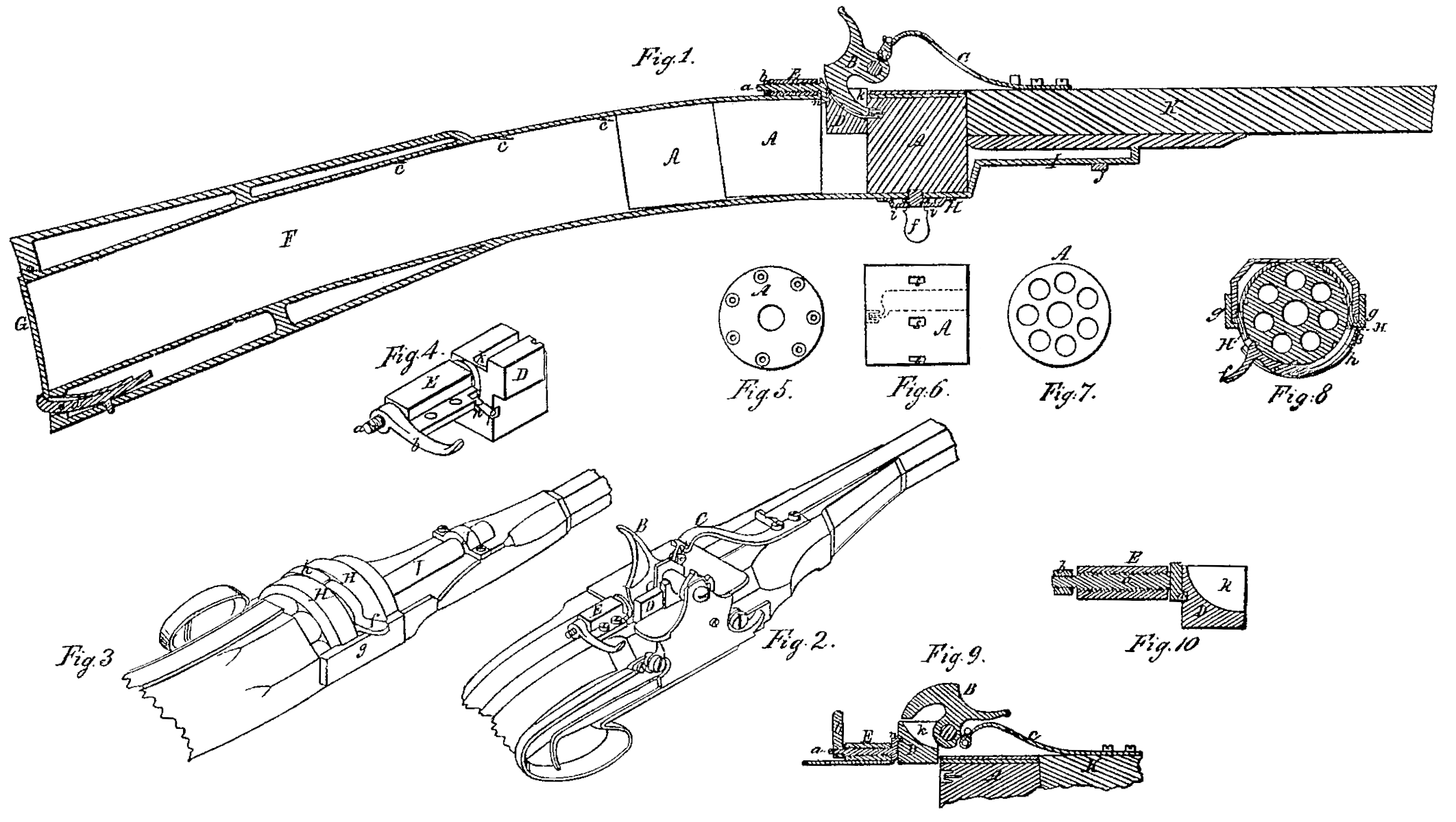
Figure 1 is a longitudinal vertical section. Figs. 2 and 3 are perspective views, and Figs. 4, 5, 6, 7, 8, 9, and 10 are detached portions of the same.
The nature of my invention consists in making the breech-stock of the gun tubular, the tube communicating with the breech of the gun-barrel for the purpose of receiving a number of shot-charged cylinders in such a manner that as soon as one is discharged of all its loads it may be easily and quickly taken from the gun, as herein set forth, and another cylinder made to take its place by simply dropping the muzzle of the gun.
AAA, Figs. 1, 5, 6, and 7, are the cylinders.
F is the tubular stock, into which nine of the cylinders are placed through the opening at the lower end of the stock, which opening is closed by the cover G and secured by the spring-catch d.
c c c are springs placed on the inside of the tubular stock for the purpose of preventing the cylinders from dropping in said stock after they have been brought up toward the barrel K.
B is the hammer, and C is the mainspring.
D is a tumbler placed immediately under the hammer B, and is made to press and retain the cylinder, which is between it and the rear end of the barrel in the position for being discharged, closely against the barrel, thereby preventing the escape of any fire or powder at the junction of the cylinder with the barrel; and the manner in which this is effected is as follows, viz:
On the upper surface of the breech the nut E, Figs. 1, 2, 4, and 10, is secured. The screw a, which fits the nut E, is turned by the lever b, and has attached to its front end a disk or plate having the pin in projecting from its front surface. The pin in plays in a slot, p, Fig. 4, cut in a diagonal direction across the rear surface of the tumbler D. When the hammer B is cocked, by lifting the lever b the tumbler will be raised to the position shown in Fig. 9, thus allowing clear space for a fresh cylinder to be brought to the barrel from the stock, as described. When the fresh cylinder is in its place the tumbler D is brought down behind it by depressing the lever b, and the same depression of the lever turns the screw a in the nut E, thereby forcing the tumbler. D forward against the rear end of the cylinder, which in its turn is brought close to the rear end of the barrel. The tumbler D has a recess, k, cut in it for the purpose of allowing the hammer to have free access to the cap on the nipple of the cylinder. This recess incloses the cap to be discharged and hits it off from all communication with the other caps on the cylinder.
H, Figs. 1, 3, and 8, is a cover, curved to fit the form of the cylinder, sliding on ledges g g, (seen most distinctly in Figs. 3 and 8,) and made to run backward immediately under the cylinder, which is in position for being discharged. The cover H has a transverse slot or opening extending across nearly its whole width, in which opening the tumbler f plays from side to side of the cover H. The cylinder A, Fig. 6, has notches s s cut on its periphery. After one load has been fired from the cylinder, and it is desired to bring the next charge round opposite the barrel, the tumbler f is pushed into the position shown in Figs. 3 and 8 and its tooth made to take into one of the notches s on the cylinder. Then by pushing the tumbler in a reversed direction to its last movement until it strikes against the spring h the cylinder is made to revolve in the breech of the gun to the point where a fresh charge is brought opposite the barrel. The cover H is of a double thickness, and the tumbler f has pins i i, Fig. 1, extending from each of its sides into the space between said thickness, for the purpose of preventing said tumbler from getting out of the opening in which it plays. The spring h, placed on the cover H immediately over and pressing onto the tumbler f, serves a double purpose. One of its offices is to prevent the cylinder from being turned too far. This it does as follows, viz: The tumbler f has extending from its outer surface, immediately over its tooth, a trigger or handle, by which it is moved, and when the cylinder is turned this trigger or handle comes in contact with the spring h precisely as the bore of the cylinder comes opposite the bore of the barrel. The other office of the spring his to prevent the tooth of the tumbler from slipping out of the notch s in the cylinder while said cylinder is being revolved.
The manner of using my improved repeating-rifle is as follows: The tubular stock F being filled with the cylinders A through the opening at the lower end, the hammer B is cocked, the tumbler D thrown up in the manner already described, the muzzle of the gun is dropped, and a cylinder falls into its place to be discharged. The tumbler D is now brought down behind the cylinder, and is made to press it against the barrel in the manner hereinbefore set forth. The cylinder being adjusted by means of the tumbler f, the hammer is made to strike the cap in any well-known or usual manner, and one load has been discharged. The hammer is immediately cocked, the cylinder readjusted by the tumbler f, and a second discharge is made. Thus the operation is repeated of cocking, loading, and firing until all the loads of one cylinder are discharged. The hammer is then again raised, the tumbler D again thrown up, the cover H thrown forward, (the rod l attached to its front side sliding under the strap J, thereby keeping said cover in line,) and the empty cylinder drops out. The sliding cover H is thrown back in its place, the muzzle of the gun dropped to cause a fresh cylinder from the hollow stock to take the place of the one just removed, the tumbler D brought down behind and made to press it forward, and thus the operation is repeated until all the cylinders are discharged.
By placing nine cylinders in the tubular stock, each cylinder containing seven loads, one man, with but little practice, will be able to discharge this fire-arm sixty-three times in less than three minutes.
Having thus fully described my improved repeating-rifle, what I claim therein as new, and desire to secure by Letters Patent, is—
1. The tubular breech-stock, communicating with the bore of the barrel, for containing a series of shot-charged cylinders, combined with the springs c c, the retaining-tumbler D, the sliding discharging-cover H, the revolving tumbler f, and the spring h, substantially in the manner and for the purpose herein set forth.
2. The manner of pressing and retaining the shot – charged cylinders firmly against the breech of the barrel by means of the tumbler D, the screw-rod a, the nut E, and the lever b, substantially as herein set forth.
L. H. GIBBS.
Witnesses:
Z. C. Robbins,
Joseph Hardy.