
US 677
UNITED STATES PATENT OFFICE
HENRY DANIELS AND CHAS. DANIELS, OF CHESTER, CONNECTICUT.
IMPROVEMENT IN REPEATING OR MANY-CHAMBERED FIRE-ARMS.
pecification forming part of Letters Patent No. 677, dated April 5, 1838.
To all whom it may concern:
Be it known that we, HENRY DANIELS AND CHARLES DANIELS, of Chester, in the county of Middlesex and State of Connecticut, have invented an Improvement in Repeating or Many-Chambered Fire-Arms; and we do hereby declare that the following is a full and exact description thereof.
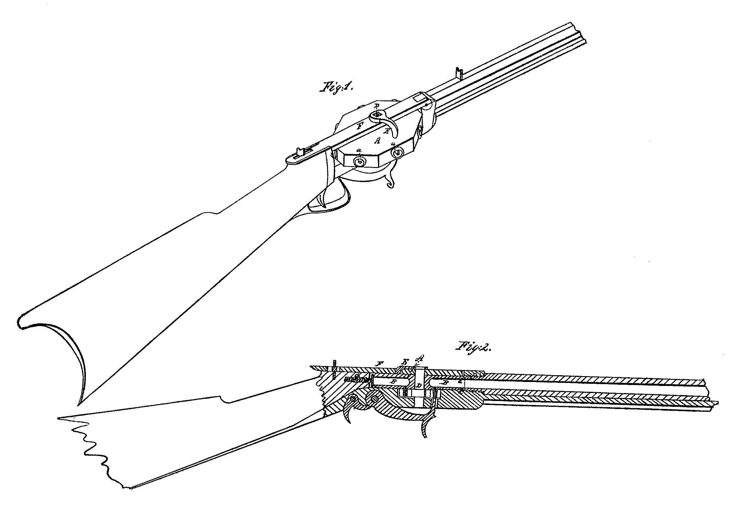
Figure 1 in the accompanying drawings shows a perspective view of one gun; and Fig. 2, a section thereof, showing the interior of the chambered receiver and other parts connected therewith.
In both drawings the same letters of reference are used to designate the same parts.
A A is the receiver, which is perforated, to contain the charges. It will be seen in Fig. 1 that this is made octagonal on its periphery, which form we prefer to that of a circle as being more secure and presenting other advantages. It may, however, be made circular and still have the projecting rim around the chamber, which constitutes a principal part of our improvement.
B B are the chambers, which are to contain the load, and these chambers have each a projecting rim, a a, which may be made conical, there being an excavation or recess at the back end of the barrel, into which said conical rim is to fit accurately. Instead of making the projecting rim conical, I sometimes make its outer edge rounding, thereby avoiding a sharp edge and causing it to enter its proper recess the more smoothly. In order to cause the projecting rim to enter the recess provided for it at the back end of the barrel, it will be evident that the receiver must be made to recede and advance as the respective chambers are made to coincide with the bore of the gun, carbine, rifle, pistol, or other fire-arm, and this we effect in the following way:
D is an axis, upon which the receiver revolves, which axle is made oval, or is otherwise so formed in that the part of it which passes through the receiver that by turning it round it shall operate as a cam or eccentric and serve to force the rim of the chamber into the recess of the barrel and confine it firmly there during the discharge.
E is a short lever, by the turning of which the axle is made to revolve and the receiver caused to advance or allowed to recede, as may be required. This lever is attached by a neck or collar to the upper stock-strap, F, so that when this shaft is turned up to change the receiver it need not be removed. The upper end of the axle which is squared, passes into an opening in the neck of this lever.
A spiral, zigzag, or other spring, G, is inserted in the stock, as shown in the drawings, and bears against a plate of metal, which comes into contact with the periphery of the receiver, bearing against it with sufficient force to hold it in its place, and yet allowing it to turn round smoothly.
The upper stock-strap, F, is hinged to the barrel, as shown in the drawings, and when in place is held down by a turn-buckle, catch, or other similar contrivance.
The mode of affixing the percussion-caps and of constructing the lock is similar to that adopted in some other guns, and will be manifest upon inspecting the drawings.
What we claim as our invention, and wish to secure by Letters Patent, is–
1. The formation of the projecting rims around the mouth of the chambers, with the corresponding recesses at the back end of the barrel, as described.
2. The forming of the revolving axis which passes through the receiver in such a way as that it shall form the said rims into their corresponding recesses and hold them firmly there during the discharge of the piece, together with the use and arrangement of spiral or other springs within the breech.
HENRY DANIELS. [L. S.]
CHARLES DANIELS [L. S]
Witnesses:
THADDEUS BEACH,
AMZI P. PLANT.