
US 524743
UNITED STATES PATENT OFFICE.
CARL VON PECKER, OF VIENNA, AUSTRIA-HUNGARY.
DOUBLE BARRE LED REVOLVER.
SPECIFICATION forming part of Letters Patent No. 524,743, dated August 21, 1894.
Application filed April 4, 1893. Serial No. 469,055. (No model.)
To all whom it may concern:
Be it known that I, Carl von Pecker, a subject of the Emperor of Austria-Hungary, residing at Vienna, Austria-Hungary, have invented new and useful Improvements in Hand Firearms, of which the following is a specification.
The object of this invention is to provide a fire arm especially a revolver, having such parts and mechanism that a series of double shots or a series of single shots (twice in number as the series of double shots) as desired can be fired off; the firearm is simple, durable and strong in construction as well as accurate and reliable in operation.
The invention consists in the improved fire arm, in the arrangement of two series of cartridge chambers in the cylinder, in the mechanism for firing the cartridges singly or in series of two, and in the combination and arrangement of the various parts hereinafter more fully described and claimed.
Similar letters and figures of reference indicate corresponding parts throughout the several views.
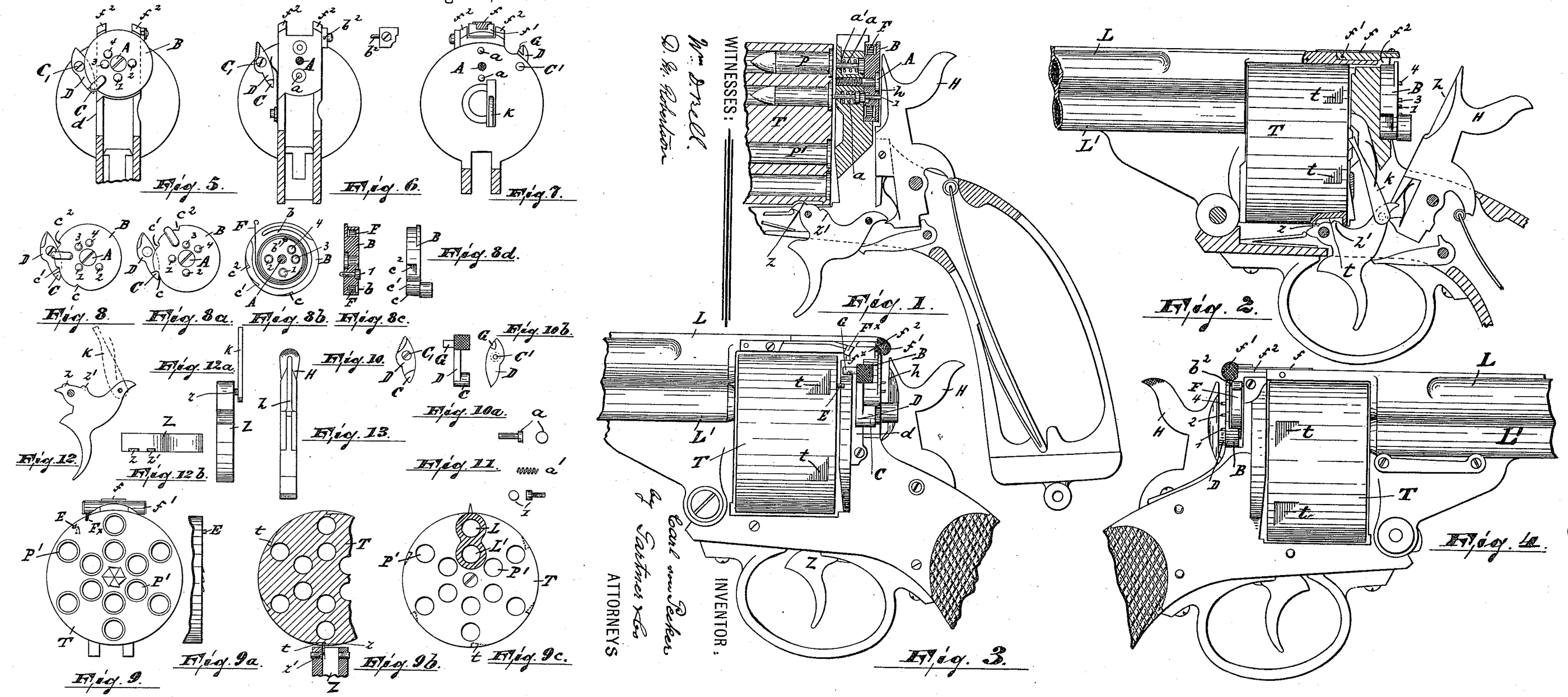
Figure 1 is a longitudinal section, partly broken away, on the line x—x, Fig. 5. Fig. 2, is a similar section on the line y—y, Fig. 7. Figs. 3 and 4 are respectively left and right side elevations of the fire arm, partly broken away. Figs. 5, 6 and 7 are cross sectional views on the lines z—z, v—v and w—w, respectively of Fig. 1, taken in the direction of the arrow p. Figs. 8, 8^a, 8^b, 8^c and 8^d are detail views of the firing pins of the firearm illustrating certain positions of the same. Figs. 9, 9^a, 9^b and 9^c are detail views of the cylinder containing the cartridges, illustrating various positions assumed by the same in firing. Figs. 10, 10^a and 10^b are respectively front, side and rear views of the locking device for the firing pins. Fig.11 represents details, in side and front elevation of the construction of the firing pins. Figs. 12, 12^a and 12^b are respectively front, side and top views of the trigger and Fig. 13 is an end elevation of the hammer.
In said drawings. A represents the axis in form of a screw around which turns the disk B, carrying the firing pins 1,2,3 and 4. The disk Bis provided with a circular groove b in Which is arranged a spiral spring F, one end of which is secured as at b’ to said disk B, while the other is secured to a pin b°of the frame of the firearm. The firing pins 1, 2, 3 and 4 rest against two similar pins a a controlled by spiral springs a’. The firing pins 1, 2, 3 and 4 transmit the action of the hammer H and also of its flattened surface h through the pins a to the fulminate cap of the cartridges P and are returned by the springs a’, after firing, into their normal position. The respective arrangement of the pins 1, 2, 3 and 4 and a, a is such, that the pins a a are arranged diametrically opposite to each other, while the pins 2 and 3 are placed on either side of and separated from pin 1 by a quadrant of the disk, and the pin 4 one eighth of said disk from the pin 3. By this arrangement, when the disk is turned, the firing pin 1 may be brought opposite and in contact with the lower pin a or the pin 4 in contact with the upper pin a or else both pins 2 and 3 in contact with both pins a, a. Thus either the cartridges in the upper or lower chamber may be discharged singly or both may be discharged at once.
To move the disk B and to register it in its proper position to accomplish the above described operations, its periphery is provided with three notches or teeth c, c’ and c^2, engaged by a tooth or pawl C arranged on a lever D pivoted on the frame of the firearm as at C, (see Figs. 5 and 6).
The cylinder T is provided with two annular sets of cartridge chambers P’ P’ which register with the barrels L, L’ arranged in the same vertical plane. The cylinder T is moved forward in the ordinary manner after each discharge and the movement of the cylinder backward between shots is prevented by the engagement of one or the other of the two. projections z—z’ of the trigger Z which enter suitable recesses t in the cylinder. When the barrel is to move forward, these two projections z—z’ lie in the same horizontal plane and thus clear the notches or recesses t. The cylinder T is also provided on its inner periphery with a pin or projection E for the purpose hereinafter described. On the top of the breech of the fire arm that is to say directly above and behind the inner end of the cylinder are arranged the two projections f^2 f^2 forming between them a recess adapted to receive the thumb piece f’ controlled by the flat spring f. This thumb piece f’ is raised from the recess when the revolver is to be adjusted for firing as hereinafter described and when so adjusted it is afterward lowered. Secured to the barrel below the thumb piece is arranged the spring piece F^x which normally extends inward and downward to come directly into the path of the pin or projection E on the cylinder T and to thereby stop the rotation of said cylinder. The arrangement of this pin E on said cylinder and its relation to the cartridge chambers is such that when it rests against the spring F^x one of the cartridges in the inner as well as outer cartridge chamber is in position to be discharged. The spring piece F^x is in its normal position only when the thumb piece f’ is raised from its recess. When the thumb piece f is lowered, the spring F^x is pushed out of the path of the pin E by means of the inclined surface f^x carried by said thumb piece. The lever D carries also a projection G which lies in the path of the pin E and is adapted to be depressed by said pin when said pin and projection come into engagement. The depression of this projection G actuates the lever D and thereby withdraws the tooth C from engagement with the notches on the periphery of disk B.
The operation is as follows:—If the cartridges of the inner chamber are to be discharged the thumb piece f is lifted and the cylinder T turned until the pin. E rests against the spring F^x. The disk B is then turned until the pin 1 and the lower pin a are in line in which position the tooth C of lever D slips into one of the notches of the disk B and said disk is thereby locked in said position. This position of the disk is its normal one and is indicated at Fig. 5. The thumb piece f is now lowered and the spring F^x crowded out of the path of the pin E on the cylinder. The fire arm is now discharged shot by shot until all the cartridges of the inner chambers are empty.
To fire off the outer circle of cartridges the same operation is gone through with as above described only in this case the disk B is moved against the action of spring F until the pin 4 and the upper pin a are in line. The position of the disk in this case is indicated at Fig. 8.
When the shots in both inner and outer chambers are to be discharged one after another the disk B is turned into the position shown in Fig. 8 when the outer series are first discharged. On the approach of the cylinder T to present another cartridge to the action of the firing pin, the pin E passes on to the projection G of lever D and thereby depresses the lever D and lifts the tooth C out of the second notch in the periphery of disk B. The disk B now by virtue of spring F returns to its normal position (see Fig. 5) that is the position when the lower firing pin a, and pin 1 are in line. The inner cartridges are then discharged successively.
To fire off double shots the disk B is turned into the position shown at Fig. 8″ in which the pins 2 and 3 are respectively in line with the upper and lower pins a a.
Having thus described my invention, what I claim as new, and desire to secure by Letters Patent, is—
1. In a revolver the combination with the revolver frame, the cylinder and the hammer, of a revolving disk interposed between the hammer and the cylinder and provided with a circular groove, a spiral spring in said groove and secured with one end to the disk and with the other end to the revolver frame, said disk being also provided at its outer periphery with teeth or notches, a series of ring controlled firing pins in said disk, pins adapted to be operated by the hammer to operate said firing pins, and a lever provided with a tooth and adapted to engage the notches of said disk, all parts, substantially as and for the purposes set forth.
2. In a revolver, the combination with the revolver frame, the cylinder and the hammer, of a revolving disk interposed between the cylinder and the hammer, a lever pivoted to the frame and provided with a tooth engaging said disk, and a pin secured to the rear end of the cylinder for releasing said lever, all said parts, substantially as described.
3. In a revolver the combination with the revolver frame, the cylinder and the hammer, of a revolving disk interposed between the cylinder and the hammer, a series of firing pins in said disk, pins adapted to be operated by the hammer to operate said firing pins, a lever pivoted to the frame and provided with a tooth engaging said disk, a pin secured to the rear end of the cylinder for releasing said lever and a spring provided with a projection adapted to engage said pin and thus limit the movement of the cylinder, substantially as described.
In testimony whereof I have signed this specification in the presence of two subscribing witnesses.
CARL VON PECKER.
Witnesses:
Alfred Hamburger,
Henry E. Everding.