
USA 11447
UNITED STATES PATENT OFFICE.
ELI WHITNEY, OF WHITNEYVILLE, CONNECTICUT.
IMPROVEMENT IN FIRE-ARMS.
Specification forming part of Letters Patent No. 11,447, dated August 1, 1854.
To all whom it may concern:
Be it known that I, Eli Whitney, of Whitneyville, in the county of New Haven and State of Connecticut, have invented a new and useful Improvement in Revolving-Breech Fire-Arms; and I do hereby declare that the following is a full, clear, and exact description of the construction, character, and operation of the same, reference being had to the accompanying drawings, which make a part of this specification, in which—
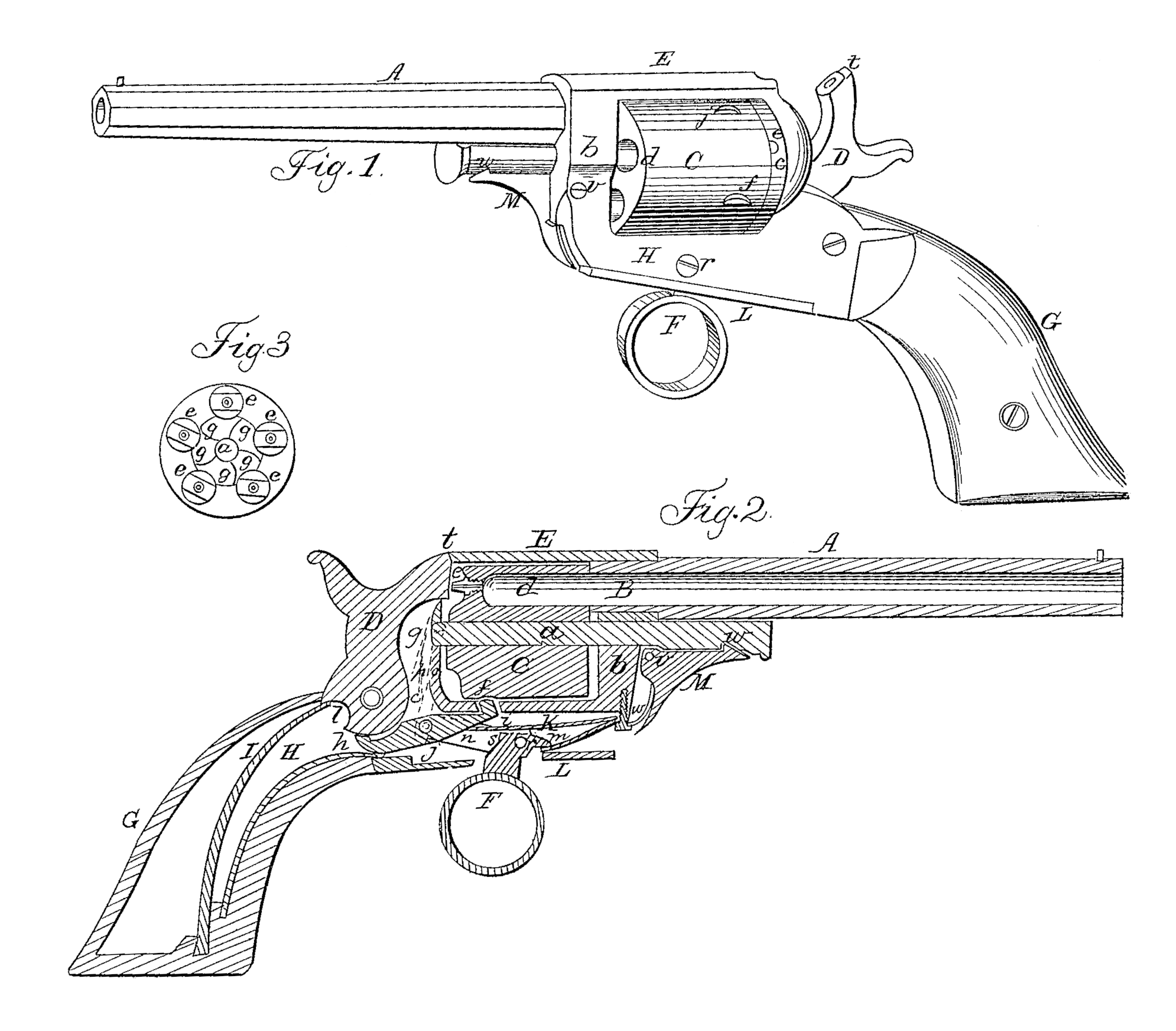
Figure 1 is a perspective view of a pistol, showing the general external appearance of the whole article. Fig. 2 is a view of a longitudinal section cut vertically through the center, showing the position and connection of the several parts. Fig. 3 is a view of the rear end of the chambered breech, showing the form and position of the ratchet by which it is to be revolved, &c.
My improvement consists in so constructing and arranging the parts as to enable me to revolve the chambered breech by pulling the trigger, and then by continuing to pull the trigger lock the chambered breech and discharge the pistol without the possibility of discharging it before the chambered breech has been revolved to its exact position and is firmly locked, while all danger of revolving it too far is prevented by the manner in which the lock-bolt is connected with the trigger, which, by means of the dog or hand, revolves the chambered breech, and it cannot recoil, because it will be held firm in that direction by the dog or hand, and the fact that the sear cannot be removed from the cock-notch in the inner end of the hammer so as to discharge the pistol, except when the lock-bolt passes into the space to lock the chambered breech, renders accidental discharge impossible when the whole is in order for use; and in making the frame all in one piece, with a top bar, not only to strengthen the frame, but also to serve as a foil for the comb of the hammer to strike against to prevent battering the cones, &c.; and in the manner of using the spring-lever catch and rod from falling out while removing or changing the chambered breech.
I make the barrel A of cast-steel, in the usual way for revolving-breech fire-arms, and attach it to the frame by a male and female screw, as seen at B, Fig. 2. I make the revolving chambered breech C of cast-steel, with a cylindrical hole through its center longitudinally, to receive the rod or mandrel a u, which passes through the center of the front shield, b, and into the recoil-shield c, to sustain the chambered breech in the frame and to allow it to be revolved when necessary; and I make five or more chambers in this breech for receiving the charges, one of which is shown at d, Figs. 1 and 2, and all five are indicated by the nipples or cones e e, &c., Fig. 3; and on its periphery, toward the rear end, I make an equal number of depressions or spaces, of the form shown at f f, Fig. 1, (as best suited to receive the bolt i,) to receive the locking-bolt i, as shown at f, Fig. 2. On the rear end of this chambered breech C, I make a number of notches (equal to the number of chambers) in the form of the teeth of a ratch-wheel, as shown at g g, &c., Fig. 3, in which the point of the dog or hand is to work to revolve it.
I make the hammer D in the usual way, except that upon the upper part I make a comb, t, Fig. 1, to strike against the top bar, E, of the frame, as seen at t, Fig. 2, to prevent battering the cones or nipples or striking the cap too hard at any time.
I make the sear h and locking-bolt i in one piece, which rocks on a fulcrum-screw at j, so that when the hammer ID is drawn back to the position of being cocked, as seen in Fig. 1, the sear-spring K (being stronger than the lock-bolt spring k) will force the sear into the cock-notch l in the inner end of the hammer, and thereby force down the front end, i, (in opposition to the spring k,) and unlock the chambered breech, so that it will be ready to be revolved (by pulling the trigger) to the position for being discharged.
I make the trigger F of the ring kind, as shown, with a projecting part in front, where it is acted on by a spring to throw the ring F forward, as shown at on, Fig. 2, and with a lever, n, projecting backward. To the rear end of this lever n, I attach, by a joint-pin, a dog, hand, or ratchet, o, the point of which works in the ratchet-wheel or notches g g, &c., Fig. l 3, to revolve the chambered breech when the trigger F is drawn back. This dog or hand o is pressed into these notches g g, &c., by a spring, p, the upper end of which presses against an inclined plane, q, in the recoil-shield, all as shown in red dots, &c., in Fig. 2. The trigger F works on a fulcrum-screw at, so that when the ring is drawn back the prominent parts will press against the spring k to force the lock-bolt i into the space p, to lock the chambered breech after it has been revolved. This prominent part S may be made adjustable by a screw, or otherwise, so that it will always exert the proper amount of force on the spring k. The trigger-plate L is made of malleable iron and secured by screws in the usual way, or otherwise.
I make the frame E b H g G of malleable iron or other suitable metal by casting it in one piece, so that the front and recoil-shields b and c are firmly attached to each other by the bottom bar, H, and the top bar, E, while the top bar, E, also serves as a foil for the comb t of the hammer to strike against, as before described.
I make the rod or mandrel a u for holding the chambered breech in the frame with two notches at a and u, and I make the head part flat on the side next the barrel, to keep the notched side in the right position. To secure this rod or mandrel in its place I use a spring-lever, M, with a catch, as at u. This lever works on a fulcrum-screw at v, and the catch is thrown into the notches by the spring w, so that when the chambered breech is in its place, as represented in the drawings, the catch will be forced into the notch at it, to hold the rod firmly in its place, and when the rod is drawn out sufficiently to allow the chambered breech C to be removed the catch will be forced into the notch at a. and prevent the rod from falling out. This lever is worked by the thumb or finger applied to the extremity next the trigger.
Having made and arranged the several parts, charged the chambers in the breech, put on the caps, &c., to discharge the pistol I drawback the hammer in the usual way for cocking until the notch l in the inner end of the hammer comes over the sear h, when the sear-spring K(being stronger than the spring k) will force the Sear into the notch l, and of course force down the lock-bolt i, and thus unlock the chambered breech. I then pull the trigger F, when the lever a will force the dog or hand o into one of the notches gg, &c., Fig. 3, and revolve the chambered breech to the proper position to discharge the pistol, at which time the space f will be exactly over the lock-bolt i, all as represented in Fig. 2, when the prominent part s of the trigger F will press against the spring k and force the lock-bolt i up and lock the chambered breech, in doing which it of necessity draws the sear h out of the notch l, when the mainspring I will force forward the hammer D to ignite the cape (all as shown in Fig.2) and discharge the pistol. When the trigger F is released the spring in will again throw it forward to the position shown in Fig. 1, which will draw the dog or hand o down, so that the spring p will press its point into the next lower notch g g, &c., Fig. 3, on the rear end of the chambered breech, and be ready for again cocking, revolving, locking, and discharging the pistol.
What I claim as my invention, and desire to secure by Letters Patent, is—
1. The method of constructing the sear and lock-bolt in one piece, combined with the method of operating the same by the trigger and spring k, so that the sear cannot release the hammer except when the chambered breech will be firmly locked in its proper position, when constructed, combined, and operated substantially as herein described.
2. The combination of the trigger with the spring k and the lock-bolt i, (when the lock bolt is of the same piece as the sear) for locking the chambered breech and discharging the pistol, when constructed and combined substantially as herein described.
3. The combination of the three springs w, m, and k, (when they are all secured with one screw,) with the catch lever M, trigger F, and the lock-bolt i and sear h, when the whole is constructed, arranged, and combined substantially as herein described.
ELI WHITNEY.
Witnesses:
S. Ransom,
R. Fitzgerald.